Introduction

Use this guide to replace a broken data port in your Canon Pixma MP480 Printer. Replacing your data port will help you regain your USB and card readers.

The data port is a piece of hardware that is responsible for transmitting and receiving memory from your device to your printer. With a broken data port, flash drives and/or memory cards cannot connect and retrieve data from your printer to your laptop or device. Your printer's front data port (USB and Memory Card Reader) may need replacement if you plug in a flash drive or memory card reader and the printer does not recognize it.

Before using this guide, consult and review the troubleshooting page. Oftentimes, issues can be solved without replacing the data port.

Before beginning, ensure that your printer is powered off and disconnected from any external power source.

  1. ofUToxLQNCZ2HO1M
    ofUToxLQNCZ2HO1M
    qMuoFBO3wZXf2Uak
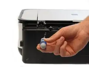
    • Remove the two 7.9 mm screws using a Phillips #1 screwdriver.

  2. b2BGODeXYFwttEkU
    • Lift up the back cover to remove it.

    • You may need to lift firmly as it requires quite a bit of force.

    "quite a bit of force" is almost an understatement, I found 2 clips along the bottom of that rear piece, one at the far left one around the middle (indicated by an arrow on the underside of the machine) - undoing these required much persistence with a screwdriver

    Perhaps Fuzz -

    Thank you, Perhaps Fuzz. Thank you.

    Marji Zintz -

  3. tI1uXZAEJ2npisIV
    • Open the front tray.

  4. mgPdKhjJ1FmS5Cw3
    mgPdKhjJ1FmS5Cw3
    vLH5mhugWcJC5E3H
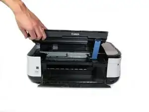
    • Open the scanner compartment.

    • Make sure the blue lever locks into place to keep the compartment open.

  5. QUiyjWRRDx2DYjAn
    QUiyjWRRDx2DYjAn
    PwaZVwcng324MBNk
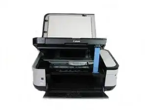
    • Remove the blue lever from its slot by pushing it back and twisting clockwise.

    • Close the scanner compartment and cover.

  6. ODKxhbUjCbwwC61m
    ODKxhbUjCbwwC61m
    VTTvnOP2ZsXoHL5C
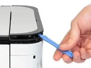
    • Pry open the side cover with the plastic opening tool.

  7. HJMrafeNBYxXWvMC
    HJMrafeNBYxXWvMC
    cZjooH63AqHQRFa2
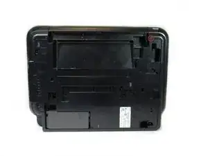
    • Flip the printer over so that the bottom of the printer is facing you.

    • Use the plastic opening tool to remove the corner of the side panel from the plastic pin.

  8. ydLX6TeDiv1QeF5F
    ydLX6TeDiv1QeF5F
    wRnOCOtihWZ6SEqH
    • Use the plastic opening tool to loosen the side panel from the bottom of the printer.

  9. O2rCJDoUxStVDfWA
    O2rCJDoUxStVDfWA
    mYgYRYyfiwIMiOJn
    • Using the plastic opening tool, pry off the top cover of the LCD assembly.

    • Pry around the front and side edges for the easiest removal.

  10. wNiOeipQKDTkXBQE
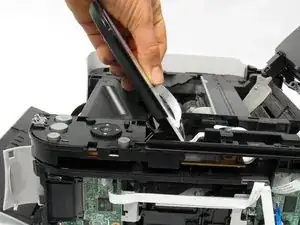
    • After removing the top cover of the LCD assembly, remove the LCD using the plastic opening tool.

  11. vxkZ2J3NxGjpwQNi
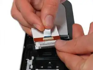
    • Gently pull the ribbon cable to remove the LCD completely.

  12. 3mmDxvln2bu2ifrT
    • Locate the buttons on the top of the printer.

  13. NgF2T6dfAMRSEhWZ
    • Using the plastic opening tool, gently pry under the button cover to remove it from its fixture.

  14. hYnKnVJBTKqnF2sG
    hYnKnVJBTKqnF2sG
    GdvOADBiPwHyYk6p
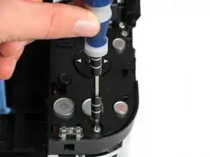
    • Remove the five 7.7 mm screws using a Phillips #1 screwdriver.

  15. cFSKUFwSOjyMTqXt
    cFSKUFwSOjyMTqXt
    NssiDCt2MYCGLmdH
    • Using the plastic opening tool, gently pry around the cover behind the LCD screen to remove it from its fixture.

  16. lVTCDKYa1hNMhrf6
    lVTCDKYa1hNMhrf6
    guRxlLFshoxZP1NZ
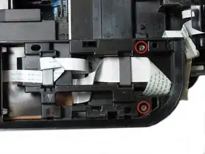
    • Remove the two 7.8 mm screws using a Phillips #1 screwdriver.

  17. oSDoNGq4cmFNESIQ
    • Gently pull the LCD screen up to remove it from its fixture.

  18. MKWRshtqq2ADwJjV
    • Use the plastic opening tool to pry off the plastic button assembly.

  19. oKHKSqxyScLWjbxM
    • Gently pull the plastic button assembly up to remove it.

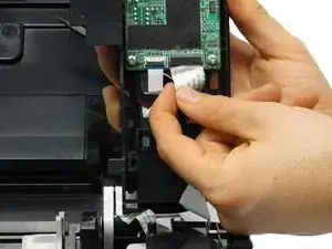
    • The plastic button assembly has a ribbon cable connected on the bottom, so be careful pulling it.

  20. IM4xleYS5BrlsZCS
    • Remove the ribbon cable connected to the backside of the plastic button assembly.

  21. EMU2WHcAPOwuOMeP
    EMU2WHcAPOwuOMeP
    PEpDM4NJOAtFbPnO
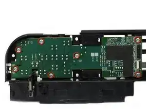
    • Remove the seven 8.7 mm screws using the Phillips #1 screwdriver.

  22. uYI1I5dJYK4oC15M
    uYI1I5dJYK4oC15M
    Kw1grHqqXZgiVMqK
    6jrMPYRRYKZX5p2H
    • Locate the spring that holds the PCB in place on the bottom left of the plastic button assembly.

    • Gently lift the spring and pull the board out of its plastic button assembly.

  23. BPW3Wv2LP4UNMPXM
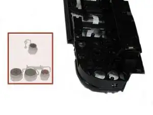
    • Remove the buttons from the plastic button assembly.

  24. tXsgQBhdTVVuqGCl
    tXsgQBhdTVVuqGCl
    quYGE5YmEyuBZXVv
    • Remove the 7.5 mm screw using the Phillips #1 screwdriver.

  25. GQad3DaXwApl5nNV
    GQad3DaXwApl5nNV
    CgqY5uMPM3MtJhEE
    • Remove the five 3.5 mm screws using the Phillips #1 screwdriver.

  26. YGQHaUDyNhJW1ruV
    • Remove the small plastic clip using the spudger.

  27. AKJRZUl1VXgOb1Mh
    • Pull the plastic inserts out of the holes in the top and bottom.

  28. sbgrTqoAPaKykbES
    • Remove the board from the printer by pulling the board towards the back of the printer.

    • This requires effort and time as the board comes out slowly.

Conclusion

To reassemble your device, follow these instructions in reverse order.

Steven MacLean

Member since: 15/01/13

86 Reputation

0 comments