Introduction

Did the LCD Screen on your Canon PowerShot S410 stop working so you can no longer see the images you are trying to photograph on the back of your camera?

Follow this step-by-step guide to help repair your LCD screen so you can get back to taking those photos!

  1. jIMwnyWSI3SXoSbo
    jIMwnyWSI3SXoSbo
    4SOZrVvgxu5N2MSw
    • Turn the camera with the bottom side facing up.

    • Locate the panel labeled "Batt. Open"

    • Place your finger on the panel and slide it in the direction of the arrow.

    • The slot will swing open revealing the battery pack.

  2. 6YAXDjDmausnZyqf
    • Pull the orange lever and the battery will spring out slightly.

  3. AyWNI1HnCVhIpWyd
    • Grasp the battery and fully pull it out of its slot.

    • When placing the new battery back in the slot, the arrow on the battery must align with the arrow on the camera.

  4. cFbwehVWr4Nw2eAQ
    • Start by laying the camera flat with the LCD screen facing up.

    • Using the Phillips #0 screwdriver, remove the 3.8mm screw in the upper right corner.

  5. dvSTvPBMAhgQZjtE
    • Position the camera with the bottom facing up.

    • Twist the screwdriver counter-clockwise to remove the 4.8mm screw.

    • Repeat to remove the two 2.3mm screws.

  6. kPvy1AKNUkMBuCrq
    kPvy1AKNUkMBuCrq
    MVPdPUXEVxHuhHam
    • Position the camera so that the rubber "AV Out Digital" tab is facing upward.

    • Slide the rubber tab to reveal the bottom screw.

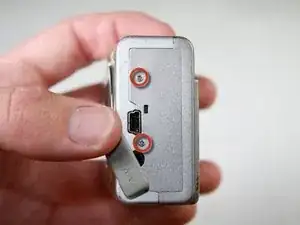
    • Using the screwdriver, remove the two 3.7mm screws.

  7. y3FmPWfWDFVpxSXW
    • Turn the camera with the back side facing you.

    • Grip the edges of the back plate, and carefully slide it off.

    • If there is any resistance in movement, double check there are no screws left in the chassis.

  8. QxQDyoIhyojEJOIn
    QxQDyoIhyojEJOIn
    TBT15nHHgYNNGr3i
    • Orient the camera as in the picture.

    • Remove the two 2.3mm outer screws using the Phillips #0 screwdriver.

    • Remove the two 3.8mm screws near the strap bracket.

    • Remove the small panel covering the mounting bracket.

    • Remove the door covering the memory card.

  9. ZMFFEAnjfkGTAbuu
    • Rotate the camera so that the bottom side is facing you.

    • Remove the 3.8mm screw below the mounting bracket using the Phillips screwdriver.

  10. SxirhUieGsC6GMvQ
    • Rotate the camera so that the front is facing you.

    • Grasp the sides of the front cover and carefully pull the front panel off of the camera.

  11. vVxdTJ2DR5FsOg2N
    vVxdTJ2DR5FsOg2N
    MYYldMokv1lBWAqC
    • Position the camera so that the motherboard is facing you.

    • A fingernail or spudger can be used to remove the plastic flap covering the motherboard.

  12. 6AkhaxXYpNkNQ1AJ
    6AkhaxXYpNkNQ1AJ
    NwlZnjCW61YiSX6a
    • Turn the camera so that the bottom side is facing you.

    • Remove the 2.1mm screw using the Phillips #0 screwdriver

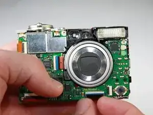
    • Grab the sides of the bottom panel and lift to expose the ribbon cable.

  13. oWlJrjYYAVJXNNyt
    oWlJrjYYAVJXNNyt
    qQ6FrvVFRkGCtSPv
    • Turn the camera so that the motherboard is facing you.

    • Using your fingernail, open the black clip holding the ribbon cable.

    • Gently pull out the ribbon cable in the direction of the cable using your fingers or tweezers.

  14. NjVqINWY5AnMBRO2
    • Turn the camera so that the LCD screen is facing you.

    • Remove the two 2.1mm screws on the aluminum tabs of the LCD screen using a screwdriver.

  15. IHRAACgEu5wuyOiJ
    IHRAACgEu5wuyOiJ
    BJQwZDryWRfwHkKW
    • Using a pair of tweezers, carefully pull the top ribbon cable out of the slot.

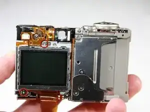
    • Grasp the sides of the LCD screen and lift off of the camera.

Conclusion

To reassemble your device, follow these instructions in reverse order.

kubayubay

Member since: 24/01/11

101 Reputation

0 comments