
Introduction
Use this guide to access LCD screen and make repairs.
-
-
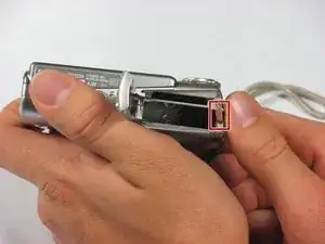
Slide the light grey tab toward the edge of the camera using your fingernail.
-
Pull the light grey tab up to open the door.
-
-
-
Slide the small brown tab toward the edge of the camera using your fingernail.
-
Let go of the brown tab when the battery pops up.
-
Grab battery and pull straight up to remove from holder.
-
-
-
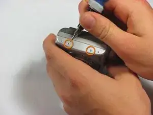
Remove the following 4 screws:
-
Two 2.8 mm Phillips #00 at the bottom of the camera.
-
Two 2.75 mm Phillips #00 on the opposite side of the wrist strap.
-
-
-
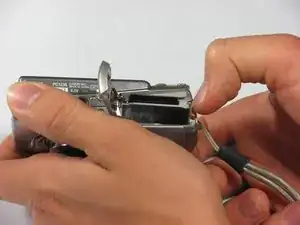
Open the A/V OUT DIGITAL flap on the side of the wrist strap.
-
Remove the 2.75 mm Phillips #00 under the A/V OUT DIGITAL flap on the side of the wrist strap.
-
-
-
On the bottom of the camera, use your fingernail to slide the light gray tab towards the edge of the camera.
-
Slide light gray door and pull up to open the door.
-
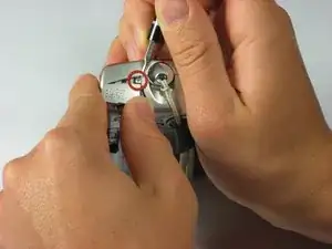
Remove the 8.35 mm Phillips #00 next to the brown tab that holds the battery.
-
-
-
Gently pull the front cover straight out from the camera. This will expose the wiring on the front of the camera.
-
-
-
Remove the one quarter bracket around the LCD screen
-
Remove the three quarter bracket around the LCD screen.
-
-
-
First, use a spudger to pry the the two tabs from the small guide pins.
-
Second, slide the bracket to the right as indicated in the second picture while lifting up. A small tab is holding the final bracket in place.
-
Remove the square metal bracket.
-


To reassemble your device, follow these instructions in reverse order.
