Introduction
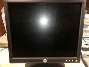
Here is an older (2005) model Dell monitor. This one had a blinking green light. That is a common error for this model. The error is caused by either bad capacitors or two failed transistors, on the power supply board. For now, we are just looking into getting to the power supply.
-
-
Dell 174FPb with blinking power light
-
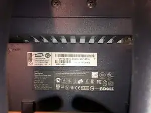
Here is the Dell Data sheet for this monitor.
-
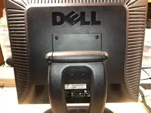
Solid stand for this size monitor. It's the first thing to be removed.
-
-
-
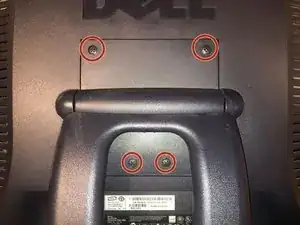
These are the four screws to be removed
-
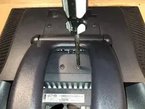
Remove the four (4) Philips head screws
-
To remove the stand, tilt the front end slightly up and then slide it down and out
-
-
-
The machine screws are 4mm x 10mm
-
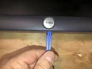
Next we need to separate the case. Insert an opening tool just below the Dell badge
-
and turn the tool. There are tabs that hold the parts together. They release with prying and will not release by simply sliding the tool.
-
-
-
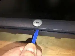
Continue to release all of the tabs on the bottom first.
-
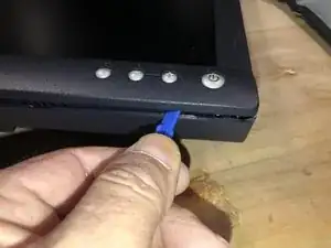
The move up the sides, continuing wit the same motion.
-
As more and ore tabs get released, the tasks will get easier. The gap between front and back will widen.
-
Once all the tabs are released, the back will simply come off.
-
-
-
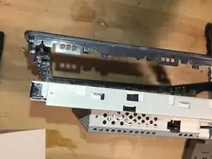
Here is the back cover, not damage and it can be placed aside for now.
-
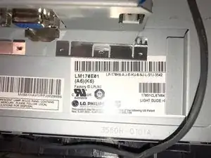
Here is a look at the data label of the panel. It is a LG Philips panel and the datasheet for this panel, will be added to the guide.
-
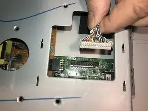
Here is the connector for the front button bar.
-
-
-
To remove it simply pull on the connector. No tabs or another release on it.
-
Here is the DB15 female VGA connecto
-
Remove the two (2) standoff with a 5mm nut driver or similar.
-
-
-
Standard Jack Screws for the D-sub connector
-
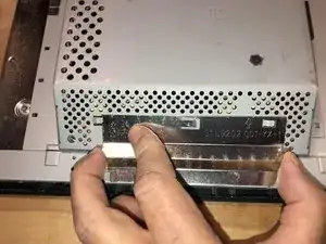
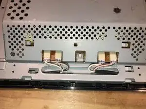
Next remove the backlight connector cover
-
Slide it horizontally into the opposite direction of the arrow stamped on it.
-
-
-
then simply pull it off
-
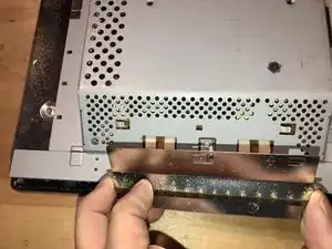
Here are the connectors for the CCFL backlight. Identifiable by those connectors.
-
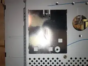
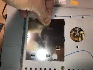
Next we remove the cover for the LVDS cable.
-
-
-
This is a bit flimsy so care must be taken not to bend it to much
-
Just slide it into the opposite direction of the arrow stamped on it.
-
This shows the tabs used to connect the cover to the chassis.
-
-
-
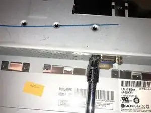
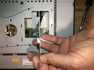
Here is the LVDS cable
-
which disconnects by simply pulling up on the connector. The image is only to document that there is not tab or other locking mechanism on the connector. Do not pull on the wires to remove it.
-
Disconnect the CCFL connectors the same way. Pull on the actual connector, not the cable. No lock on the connectors, just a tight fit.
-
-
-
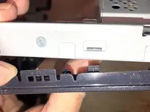
Next is the removal of the front bezel. It simply clips on. Slight downward pressure on the bezel,
-
on both sides of the panel,
-
will completely release the bezel, which includes the front bottom bar.
-
-
-
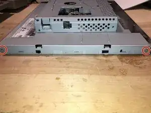
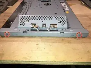
To clear the chassis with the power supply board and the Main board, we have to remove
-
these two screws on one side,
-
New line.and these two on the other side.
-
Removal of those four screws
-
-
-
allows to remove the chassis of the panel.
-
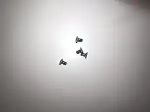
Here are the four M3 X 5mm Philips screws
-
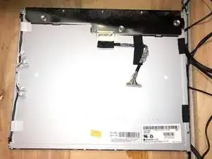
The panel can now be placed aside. It is no longer needed until reassembly.
-
-
-
Here is the panel side of the chassis
-
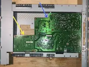
Is the main board or Video board (AD board for some)
-
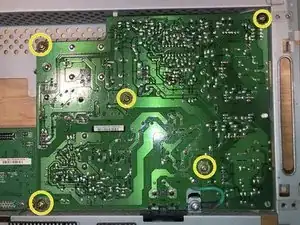
Power supply board
-
Remove the five (5) Philips head screws that hold the power supply board to the chassis.
-
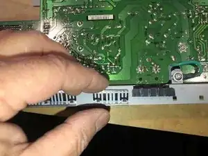
Next remove the stopper for the AC connector. It's a bit tricky. Do no try to pry it out. It actually just slides up on the sheet metal.
-
-
-
and then it slides over onto that edge. Again, no reason to try and pry it out.
-
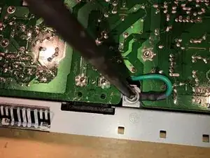
Remove the Philips head ground screw
-
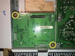
Remove the two (2) Philips head screws from the main board
-
-
-
All seven (7) screws from the two boards are identical. No reason to keep them separate.
-
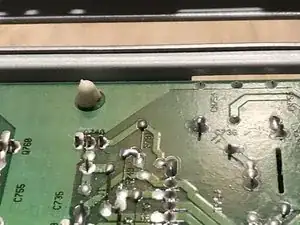
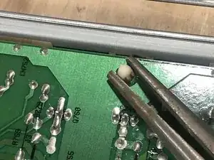
There is one plastic standoff that still holds the board on.
-
Use some small pliers (or similar tool) to squeeze the connector together, and just push the board over that connector.
-
-
-
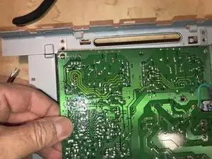
Lift up one corner of the boards
-
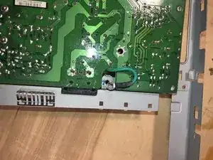
and guide the AC connector straight up
-
and out of the chassis.
-
-
-
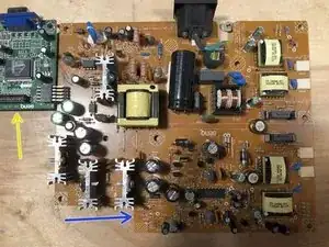
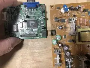
Turn both boards over.
-
Video board
-
Power board
-
Simply slide the boards apart to separate them
-
Here is the separated power board. It can now be inspected for bad capacitors as well as the chronic failure of the two transistors.
-
Q759
-
Q760
-


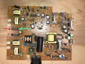
This power supply indeed suffered form failed transistors. The ones that failed were Q759 and Q760. Both are 2SC5707 Bipolar transistors. Now, question of economics. The transistors are about $2 USD plus around $6 USD for shipping. That repair will leave us with a repaired power supply, but still only have a VGA connection on the monitor. I am leaning toward spending $25 USD for a universal LCD driver adapter. That will give this monitor HDMI and DVI connections, which will provide for more connectivity options. This might make the monitor more useful for another 10 years or so :-)
