Introduction

  1. RjClG2JBB3Af5LQf
    • First: Eye Camera

    • Remove initial frame (crack off)

  2. RXeEWMUwEOVlyFfv
    • Remove 4 screws.

  3. ahqAsRMkN6HZFgYj
    • Remove cover to get to the PCB underneath

  4. oLYMJBfKSoJeblSQ
    • Remove two screws on the PCB.

  5. E4Ex34Syy4pkcNgX
    • Remove PCB from the base plastic piece.

  6. T6XnptmLI1bLEQnc
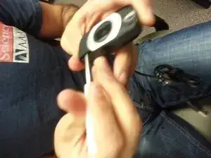
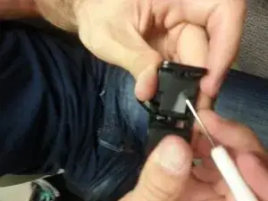
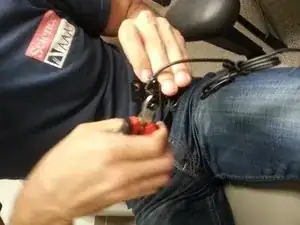
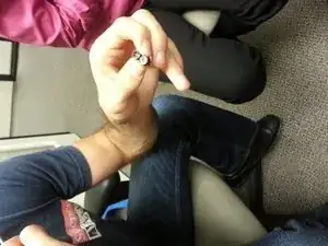
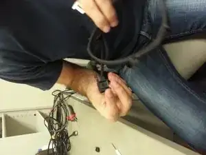
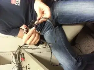
    • Break base plastic piece. Cutters work well. Be careful not to snip the wire attached to the PCB.

  7. ZAkODkxYfu1JTOQh
    • Black mold (from 3D printer) piece attaches to the PCB with 4 screws.

  8. BQpvG2TOZtwDybOf
    • Completed assembly of the eye camera.

  9. ZXysWxbQNXkoJUVr
    • Back of pupil camera is glued on. Remove with flat-head.

  10. RCWZreRiJYQTWMIk
    • Remove the black frame on the front of the pupil camera.

  11. BoNkp2MYIDhacYyF
    BoNkp2MYIDhacYyF
    dxi6YYaFDCJKdYvc
    • Once frame is taken off the front, two screws need to be removed.

  12. LPMIrDdU3jWX3jyM
    • One screw removed from the back.

  13. ChWmeyAuNxBytHsg
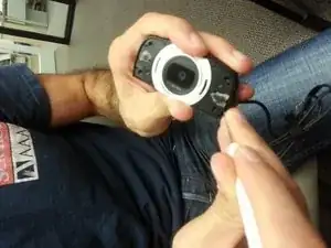
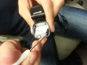
    • Front housing comes off once the screws are removed from the frame.

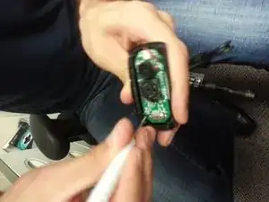
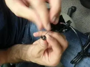
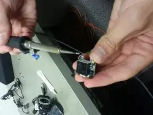
    • Twist out the silver microphone.

  14. yyMKemHUb6lf5aFI
    • Pull off bottom stand until it breaks off.

  15. i4WRnWcpERFgxymg
    i4WRnWcpERFgxymg
    ydMgJi4bCToK1Kf6
    • Remove rubber/plastic piece from the bottom

  16. ebdjJIHTfXfeDIpq
    • Remove four screws from under the plastic tape (removed from last step).

  17. bTGndddILGavkUrO
    bTGndddILGavkUrO
    CuK2BshSsoMqvSRJ
    • Bottom pops off

  18. p43KeTOAMLqfFuNR
    p43KeTOAMLqfFuNR
    SCUtCfRQqHNPNfhd
    • Separate the metal frame from the plastic assembly.

    • Avoid the cables

  19. f2oBRCF1GqKNArEt
    • Take out PCB from the plastic housing.

  20. ROGcpTKKIK3NQLdM
    ROGcpTKKIK3NQLdM
    JDVYTAjmNGFehEoP
    6RUODx6bARKYjSNn
    • Remove the rest of the black plastic housing.

  21. pDtIjkUHjWdUcZvY
    • Black plastic housing removed

  22. LBKbwZKTKS3NZNor
    LBKbwZKTKS3NZNor
    HLJJLahJgvhKeXW1
    tQQlTZ1MiJrHG5qC
    • Continue removing the black plastic housing surrounding the inner PCB.

  23. 4iOw5hnuUPrUuasw
    4iOw5hnuUPrUuasw
    O3ZD2VTEJMP3DpFK
    • PCB removed from the black plastic housing.

  24. 16ViedlgLAWeDQn6
    • Autofocus assembly.

    • Remove two screws from the bottom of the auto-focus PCB.

  25. kObjdmOXrYPHlHbi
    • Unscrew the lens

  26. UursBQCH6v4B3Ad2
    UursBQCH6v4B3Ad2
    GbKF5qCFDd3uSUgW
    • Take out the IR filter by using a scalpel for pulling out the lens tape.

  27. 4JJdZ3qfk3rHcQgK
    4JJdZ3qfk3rHcQgK
    DEWKROpJueiNePN2
    kagobfIueHObk1yJ
    • Comparison photos of completed autofocus assembly vs in-progress autofocus assembly

  28. dcIVBlXPHHJrcsxO
    dcIVBlXPHHJrcsxO
    DvBtZDYDWBFPLmo1
    • IR LEDs replaced by SMD LED

    • Soldering required here (at bottom of LED to remove).

  29. UQlmSMKbNgMjV2yX
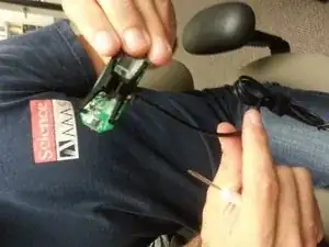
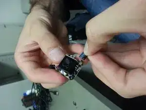
    • SMD LED info: Thick black line is near the positive side of the LED

    • Dark side (dot) is positive side on LED.

  30. OdP1DWoViyh6KuWk
    OdP1DWoViyh6KuWk
    vZMoXwm3FZAms31R
    1ifpPurBMp3vflMe
    • Insert PCB into 3d-printed frame.

  31. KEWM3AU3sfPZiwRA
    KEWM3AU3sfPZiwRA
    AQtGlByuX3HIdNVD
    • Completed assembly.

    • Sugru used for nose/head rest

Conclusion

To reassemble your device, follow these instructions in reverse order.

Silas

Member since: 25/11/13

318 Reputation

0 comments