
Introduction
Replace the pressure roller within the fuser unit for Lexmark printer models MS810, MS811, MS812, MX710, MX711, MX810, MX811.
This guide starts after the fuser unit has been removed from the printer.
-
-
Remove the two 5mm Torx T10 screws from the metal top cover. The top cover then slides off.
-
Remove the two 5mm Torx T10 screws from the front plastic cover.
-
Use a small flat bladed screwdriver to release the plastic clip in the base that is holding the front cover in place. The front plastic cover can now be removed.
-
-
-
Unplug this wire and unthread it from the hooks so that it is free to move and provide the slack that will be needed to move the fuser sleeve.
-
Slide this clip off to provide some slack in the cables at the other end of the fuser sleeve.
-
The front of the clip pulls slightly outwards to release the clip for sliding off.
-
-
-
The paper guide is remove by gently bending it upwards from the centre until the retaining pegs at one end are released from the metal frame.
-
-
-
The strong spring at each end of the fuser needs to be removed to release the pressure on the rollers.
-
A strong hook is needed to unhook the spring. The example in the picture is made from a wire coat hanger.
-
The lever at each end of the fuser can now be lifted, clearing the way to release the rollers.
-
Note how the plastic wedge is in a vertical position. The wedge must be set to this vertical position on re-assembly.
-
This wedge lifts the lever, reducing the pressure on the rollers which would otherwise create flat areas on the soft pressure roller. The printer moves this wedge to increase the pressure only when the rollers are rotating ready to print.
-
-
-
Remove the three 5mm Torx T10 screws and remove the metal plate covering the cog wheels.
-
Remove the two screws retaining the rest of the cog wheels. Do not remove these cog wheels. They will just need moving temporarily to release the fuser drive cog.
-
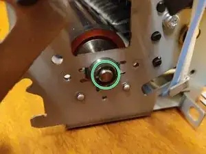
Remove the circlip retaining the fuser drive cog. A small flat bladed screwdriver can be used to remove the circlip.
-
The large black cogwheel can now be removed from the end of the fuser pressure roller.
-
-
-
Remove the three 5mm Torx T10 screws and remove the plate covering the bearing.
-
Remove the circlip retaining this end of the pressure roller.
-
-
-
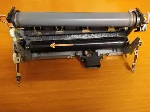
The fuser film sleeve can now be removed from above the pressure roller and left to rest on top of the fuser. It is not necessary to disconnect the fuser heater if only the pressure roller is being replaced.
-
-
-
There pressure roller axle now has the freedom to slide to the left.
-
This releases the right hand end of the axle from its mounting so that the pressure roller can be lifted upwards and removed.
-


To reassemble your device, follow these instructions in reverse order.