Introduction
The Maker Shed Learn to solder badge is a great project for beginner electronics enthusiasts. It teaches the fundamentals of electronics and soldering in a safe, fun, quick way.
-
-
Solder serves somewhat as a glue for electronics. Soldering is a process of melting a metal "filler" material into a joint between two metal surfaces.
-
Terminology:
-
Junction: A void between two metallic objects about to be filled with solder
-
Joint: An electromechanical connection formed by melting solder into the junction of two metallic materials.
-
-
-
Maker sure you have the following tools before beginning:
-
Soldering Iron
-
60/40 rosin core leaded solder
-
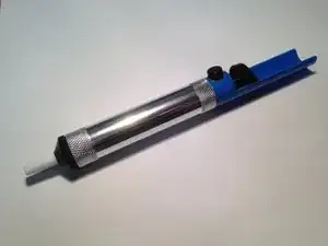
Solder sucker
-
A Heavy Object: something with a small footprint, but still heavy enough to hold the PCB in place. We suggest a hockey puck.
-
Scotch tape
-
Diagonal Cutters
-
-
-
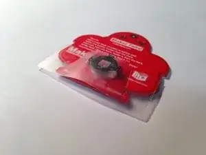
Printed Circuit Board (PCB)
-
Pinhole
-
LED spots
-
Battery pad
-
Pin and its backing
-
RGB LED (2)
-
Battery holder and CR 1220 Lithium battery
-
-
-
Make sure the soldering iron is properly plugged into the base unit and is powered on. (red power switch is located on the side of the base unit)
-
Use the dial to set the temperature to read 600 degrees Fahrenheit.
-
-
-
Hold the iron in your hand. Add a small amount of solder to the tip of the iron. It should melt instantly upon contact.
-
Immediately wipe the solder off with the wet sponge on the iron stand. [photo]
-
-
-
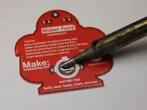
Rest the soldering iron on the battery pad to heat it up.
-
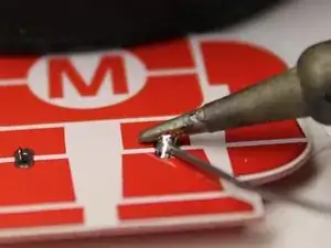
Once the pad is hot enough, begin adding solder.
-
If solder does not flow immediately when it comes in contact with the pad, remove it and allow the pad to heat up longer.
-
Apply a large gob of solder to the pad (as shown).
-
Tin the iron and return it to its stand.
-
-
-
Desoldering tools are great for cleaning up mistakes. They're really easy to use!
-
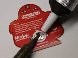
Apply a copious amount of solder to the battery pad, as explained in the previous step. [photo with copious solder, iron, and desoldering tool in play]
-
Depress the plunger in the desoldering tool until it clicks.
-
Heat up the joint until the solder flows.
-
Press the tip of the desoldering tool into the pool of solder. Simultaneously press the return button on the tool.
-
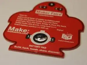
Whoop! Away goes the solder! Press the plunger down again to release the solder it collected. [photo with iron and desoldering tool in play, solder gone]
-
-
-
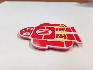
Align the battery holder tabs with the white silkscreen outline on the PCB. Use tape to hold battery holder in place, if helpful.
-
Invert the board. The battery holder tabs should extrude through the holes, as shown. If this is not the case, reposition the tabs accordingly.
-
-
-
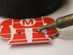
Place a heavy object on the board to keep it from sliding around on the table.
-
Rest the iron between the extruding battery holder tab and the corresponding solder pad to begin heating them up.
-
-
-
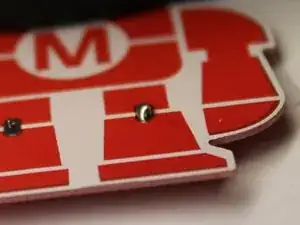
Check if the junction is hot enough. Without removing the iron, begin feeding solder into the junction between the tab and the pad. If the iron is on one side of the tab, feed the solder from the other side (as depicted).
-
Apply a generous amount of solder to the junction. The resulting solder joint should be shiny and appear as shown. If this is not the case, lay the iron back on the pad and reflow the joint until the solder liquifies again.
-
Tin the tip of the iron and then return it to its stand.
-
-
-
Repeat the previous step and solder the second battery terminal.
-
Tin the tip of the iron, then return it to its stand.
-
-
-
Cold solder joints, or "crappy" solder joints, aren't electrically or structurally stable. If a joint doesn't appear perfect, it's probably cold. Reflow the joint by applying the iron and allowing the solder to flow through the junction again.
-
Cold solder joint
-
Same joint, reflowed for perfection
-
If ever a joint seems out of luck, feel free to start over. Use the solder sucker to remove the solder in the joint, then reheat the junction and re-add the solder.
-
-
-
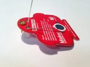
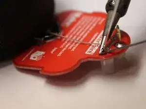
Insert the pin from the front of the board.
-
Place the board on the table so the pin is pointing upwards, as depicted.
-
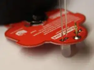
Begin heating the junction between the pin and the pad.
-
-
-
Continue heating the junction by positioning the iron as previously instructed.
-
Feed solder into the junction.
-
Tin the tip of the iron and return the iron to its stand.
-
-
-
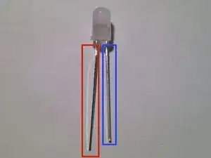
Positive lead (longer)
-
Negative lead (shorter)
-
Insert the LED into the PCB as illustrated. Be sure to match up the positive lead of the LED (the longer one) with the positive pad on the PCB (marked with a "+").
-
Bend one of the leads down tightly. This serves as a securement so the part doesn't fall away while you solder.
-
-
-
Begin heating up the junction between an LED lead and its pad by pressing the iron into the junction as illustrated.
-
Once the junction is hot enough, add solder until the joint is strong enough.
-
Tin the iron tip, then return it to its stand.
-
-
-
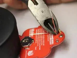
Use diagonal cutters to clip off the excess leads on the LED.
-
Cut as far to the solder join as you can.
-
-
-
Bend up the second lead and begin to heat it.
-
When sufficiently hot, apply solder to secure the joint.
-
Tin the tip of the iron, then return it to its stand.
-
Cut the lead off when you're finished.
-
-
-
Repeat the steps taken previously.
-
Position the LED and bend one lead down to hold it in place.
-
Solder the other lead in place, then clip off the excess.
-
Bend the first lead back up, then solder in it place as well. Clip the lead when complete.
-
-
-
Slide the battery into the battery holder on the badge. One side of the battery has text -- this side should be facing up (away from the PCB) as illustrated.
-
If the LEDs do not light up, chances are the battery was inserted upside down. Don't fret! The electronics are fine! Just flip the battery around and it should work.
-
-
-
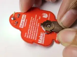
With your thumb and forefinger, press the two levers on the pin-backing to release the clutch. Press the backing around the pin exposed on the board.
-
Remove and reattach the pin when securing to clothing.
-