Introduction

I bought a kit to fix this component. The kit contained the headphone jack itself, a Phillips #00 Screwdriver and an Opening Tool.

I made do with just the above tools, but my instructions use the ideal tools should you have them.

I also replaced the rear camera at the same time, by following the excellent guide for that component.

  1. uEMEGFX5kNL1BUaZ
    uEMEGFX5kNL1BUaZ
    d5aupTQfBHnkY6hN
    • Power off the device by holding the power button until the "Power Off" popup appears. Tap the popup and wait for the device to turn off.

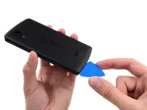
    • Insert a SIM card eject tool or a paper clip into the hole next to the SIM card slot, which is located just under the power button. Do not force the paper clip if it is too thick; instead use the head of a sewing needle.

    • Push the tool into the hole until you see the card pop out.

  2. LhjbucVW4KhyyAca
    • Gently remove the SIM card with your fingers, or a pair of tweezers if the SIM holder does not fully eject.

    • Make sure the chip is facing the rear of the phone when reinserting the SIM card.

  3. xEViSRJY4VVHfmOQ
    xEViSRJY4VVHfmOQ
    1Z4SSVIF3RKmHyfE
    cysveXG444Jp4nRI
    • Use a plastic opening tool to free the clips on the top and each side of the back cover.

    • The bottom is secured with some adhesive foam. You should be able to finally free the back cover using an opening pick. The "snaps" at the bottom edge are more like hinges, so release all others then swing the back cover off outward from the top, and these fasteners will release without breaking.

    • It's best to avoid prying around the SIM card slot and volume controls, as the plastic in these areas is very thin and likely to break from prying.

    • When you replace the cover, there is a snap about even with the flash window that must also be attached (one of three that secure the back cover to the midframe). Qi (wireless) charging may not work if this isn't secure. Apply gentle but firm pressure over the "S" in "Nexus" and slide your thumb up towards the top, and the snap will engage.

  4. BTRZoDBr3OKdfuSe
    • Remove the six 4.0 mm Phillips #00 screws that secure the midframe to the phone.

    • Ensure you retain all six of the 4.0mm screws! These hold the midframe securely and closely to the motherboard. The three small snaps on the back cover that attach to the midframe ensure the NFC antenna and wireless charging coil connectors contact securely with the motherboard, and work reliably.

    • To replace the LCD screen and digitizer, remove the additional four 4.0mm daughterboard cover screws with the same screwdriver. You may have to pierce through clear adhesive material to remove them.

  5. 3BvbgCuAHbWMQxvD
    3BvbgCuAHbWMQxvD
    dFU2GMl6CVK2L61O
    • Remove the midframe from the phone.

    • Examine the midframe and the back cover and you'll find three very small snap attachment points for the back to the midframe. These ensure that the NFC and wireless charging antenna contacts connect with the corresponding spring connectors on the motherboard. Ensure the snaps are in good condition.

  6. Oyiy1FAMsRBNFsVx
    Oyiy1FAMsRBNFsVx
    Ai1o2JTP6SWHes2S
    • Use the flat end of a nylon spudger to disconnect the battery connector.

  7. frVBkaKCOgoPsAYy
    frVBkaKCOgoPsAYy
    cq34GDWnpASPWTSV
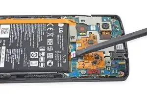
    • Use the flat end of a spudger to disconnect the daughterboard ribbon cable and pull it away from the battery.

  8. ZIeQQP3RVRHYx6Q3
    ZIeQQP3RVRHYx6Q3
    ZkXpmOus3fCXKTFm
    tSaGTMZDJD3XFcRO
    • Use a plastic opening tool to pry the battery out of its housing.

    • You may need to use a heat gun to apply a small amount of heat to soften the adhesive below the battery.

    • Do not puncture or bend the battery.

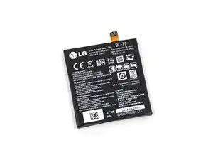
    • If replacing the battery, bag the old battery up and recycle responsibly at a suitable location.

  9. n2ATayK3owfLiG6U
    n2ATayK3owfLiG6U
    TJxKXUvK3cmasqMI
    • Use the flat end of a spudger to disconnect the left antenna cable.

  10. Dmunk4EWt5kUWcpa
    Dmunk4EWt5kUWcpa
    hqx6GJNKrDWUoxHQ
    • Use the flat end of a spudger to disconnect the right antenna cable.

    • These must be firmly secured during reassembly. Failure to secure the antenna connections will affect your reception and call quality.

  11. BtIZECIPuSFBFPPU
    BtIZECIPuSFBFPPU
    sLORMBgZOWOjEN3D
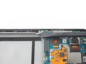
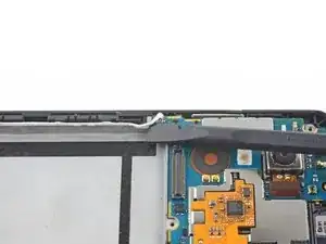
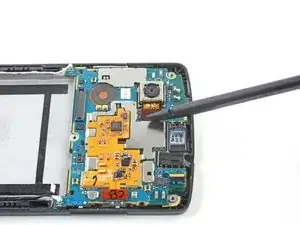
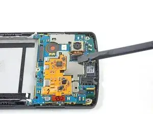
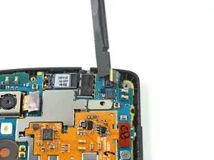
    • Use the flat end of a spudger to disconnect the ribbon cable that connects rear-facing camera to the motherboard.

  12. 2vLGDUwYvSSfVU2i
    2vLGDUwYvSSfVU2i
    Cphxbju56EhIW4Ff
    • Use the flat end of a spudger to disconnect the front camera ribbon cable.

  13. 5a2DDouuigCLtDrZ
    5a2DDouuigCLtDrZ
    tJcLaE5ufC3ckwqy
    • Gently lift the motherboard up and out of the device.

  14. sODEvZZykGxuOXjW
    • In this image, the motherboard has been removed. This is NOT required as part of this guide.

    • Use a spudger or tweezers to pull the headphone jack upward and out of the phone.

    • The headphone jack is secured by the spring tension of its contacts to the motherboard.

    • It is also secured by adhesive below it.

    • Place the new headphone jack by orienting it like the old one and pressing it gently down into the phone.

    • It is a snug fit due to the tension of its sprung contacts.

Conclusion

To reassemble your device, follow these instructions in reverse order.

anonymous

Member since: 30/03/14

296 Reputation

0 comments