
Introduction
The purpose of this guide is to replace the eyepiece (plastic rectangular piece around the viewfinder) of a Nikon Coolpix P90 if it is loose, broken, or lost.
In steps 1-2, 5, and 8, a Phillips #000 Precision Screwdriver is used to unscrew and remove all of the screws mentioned.
In steps 3-4, 6-7, and 9, there are three data connection ribbons which need to be carefully removed before the repair can continue. Failure to remove these ribbons properly will result in them becoming damaged or ripped, thereby permanently damaging your camera. So, please be careful and go slowly during this repair.
-
-
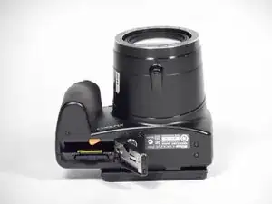
Use your finger to push the latch of the compartment door to the center of the camera body, per image 1.
-
Push the door open, and remove the existing battery with your fingers, per images 2-3.
-
-
-
On the bottom side of the camera, unscrew both 4.5 mm screws holding the bottom into place, per image 1.
-
On the right side of the camera, unscrew both 4.5 mm screws holding the side into place, per image 2.
-
On the right side of the camera, unscrew the 4.5 mm screw underneath the A/V flap, per image 2.
-
On the top side of the camera, unscrew the 4.0 mm screw on the left-side wrist strap loop, per image 3.
-
-
-
Lift up the LCD screen to reveal the two screws.
-
Unscrew the two 3.0 mm screws that hold the arm in place, per image 2.
-
-
-
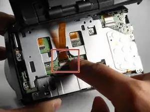
Press your finger on the top of the ribbon latch and pull it down and toward you to open the safety latch and free the ribbon, per image 1.
-
Slide the ribbon out from its socket.
-
-
-
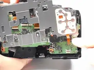
On the back side of the camera, unscrew the seven 4.0 mm screws that connect the metal plate to the motherboard, per image 1.
-
On the top side or the camera, unscrew the three 4.0 mm screws that connect the metal hinges to the camera body, per image 2.
-
-
-
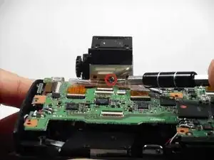
Press your finger on the top of the latch and pull it down and towards you to open the safety latch and free the ribbon, per image 1.
-
Slide the ribbon out from its socket.
-
-
-
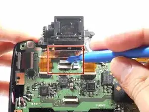
Using a plastic opening tool, carefully unlatch the safety latch that holds the eyepiece data transfer ribbon in place.
-
Slide the ribbon out from its socket.
-
-
-
Remove the eyepiece from the camera by gently pulling it back.
-
Replace the old eyepiece with a new eyepiece.
-
Congratulations, the repair is finished!
-


To reassemble your device, follow these instructions in reverse order.
One comment
Excellent Illustrative photographs and instructions