Introduction
Monitor side buttons won’t respond when pressed? It may be time to replace or clean them. This guide will walk you through the simple steps to access and replace your back panel and connected buttons.
-
-
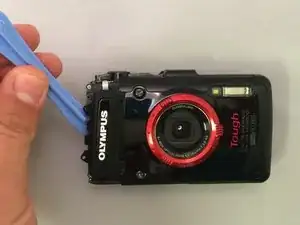
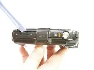
Locate the side of the camera with the connector cover.
-
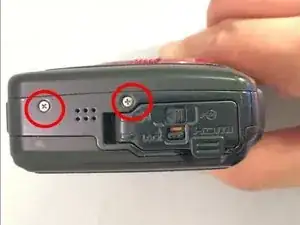
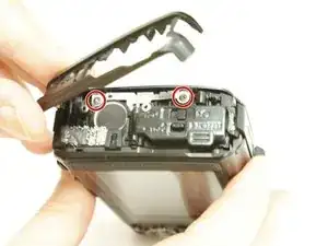
Remove the 2 Phillips #00 4.6mm casing screws.
-
-
-
Open the connector cover by sliding the tab labeled lock to revile orange.
-
Slide the connector cover lock to revile orange and the door will spring open.
-
Remove the single internal Phillips #00 3.77mm screw.
-
-
-
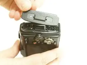
Close the door to gain access to the casing.
-
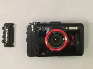
Use your fingers to remove the black plastic casing that surrounds the connector door.
-
Use your fingers to remove the next black plastic piece .
-
Remove the two screws revealed
-
-
-
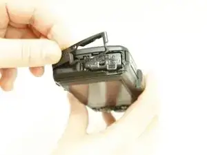
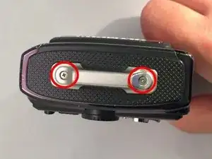
Locate the strap eyelet side of the camera and remove the 2 Phillips #00 5.3mm screws in the handle.
-
Using your fingers, take off the handle, the black casing underneath, and gently wiggle out the shiny black casing below that.
-
-
-
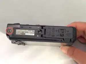
On the bottom of the camera, remove the single Phillips #00 3.5mm screw from the casing below the grip.
-
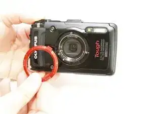
Using a plastic opening tool, gently pry the Olympus grip up and remove it.
-
-
-
Remove the 2 Phillips #00 3.4mm screws that secure the faceplate just reveled by the grip.
-
On the bottom of the camera, remove the single Phillips #00 3.4mm screw by the tripod socket securing the face plate.
-
-
-
Use a plastic prying tool to lift and remove the faceplate .
-
There will be some resistance from a sticker just under the GPS logo.
-
-
-
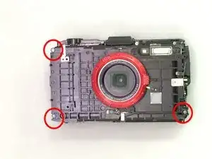
To detach the monitor screen, remove the following 7 screws:
-
Locate the flash and remove the 2 Phillips #00 9.23mm & 14.87mm screws.
-
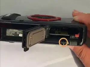
Locate the battery door and remove the single Phillips #00 3.37mm screw.
-
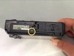
On the bottom of the camera, remove the single Phillips 3.58mm screw near the tripod socket.
-
-
-
On the face plate, locate and remove the 2 eyelet strap side Phillips #00 9.2mm corner screws and the lower battery corner Phillips #00 14.87mm screw.
-
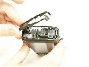
Use your fingers to unclasp the casing clips on either side of the camera and pull down the monitor casing.
-
Using the spudger to gently pry the screen away from the body of the camera.
-
-
-
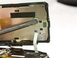
Locate the clasp for the white ribbon.
-
Use the spudger to lift the clasp releasing the ribbon
-
-
-
Locate the clasp for the orange ribbon in between the motherboard and lens box.
-
Use the spudger to lift the clasp releasing the ribbon.
-
-
-
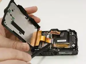
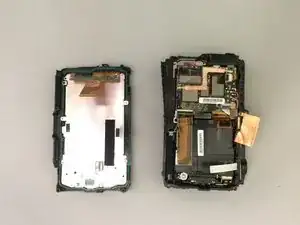
Next pry up on the white connector using the spudger to free the screen from the device.
-
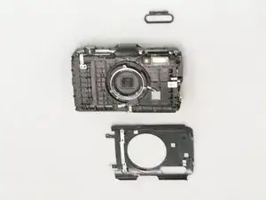
The housing and monitor will be separated.
-
-
-
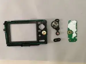
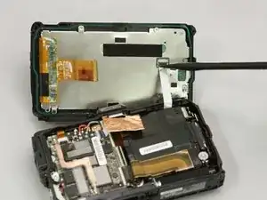
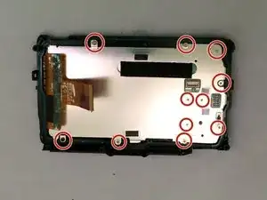
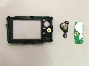
On the back of the separated monitor, remove the 10 silver Phillips #00 4.4mm screws and the 1 black Phillips #00 3.26mm screw.
-
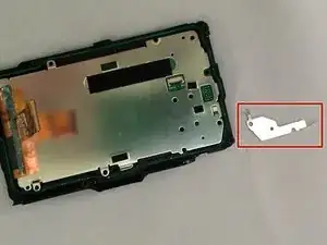
Use your fingers to remove the small corner metal triangle.
-
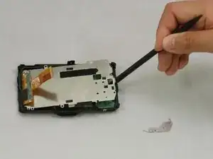
Using the spudger on the edge of the screen to lift it and remove the metal insert.
-


To reassemble your device, follow these instructions in reverse order.

One comment
Any advice on where to buy a replacement back panel for the TG-2?
epaulan -