Introduction
This guide is meant to be used as a visual supplement to the official service manual.
A guide for removing the mirror box of the Pentax LX. This is often required for general maintenance of the camera such as servicing the shutter, removing and replacing the rubber bumpers and cleaning the mirror mechanism. Previous experience with camera repair and a general knowledge of how the camera operates is highly recommended. The guide may not contain every detail and the service manual is necessary for proper adjustment and coupling of all mechanisms during reassembly. Additionally, the wiring in the LX is complex and wire colors may be hard to distinguish. When in doubt, take extra pictures so you can properly reassemble.
-
-
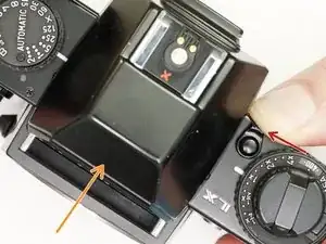
Push button and turn the prism release lever towards the prism.
-
Slide the prism off the camera body.
-
-
-
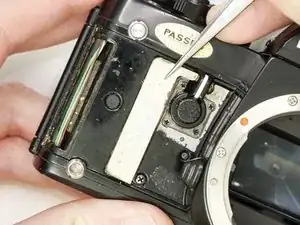
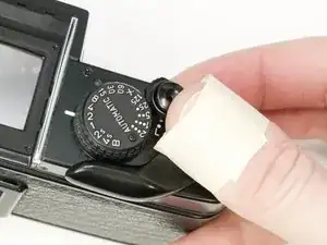
Use isopropyl alcohol to soften the adhesive along the edge of the leatherette.
-
Use a dull spudger or scraper to peel off the covering.
-
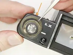
Turn the self timer lever to the 9 o'clock position.
-
Loosen the entire right side leatherette in the same manner, then work it over and around the self timer lever to remove.
-
-
-
Remove the two cover plates under the leatherette.
-
They may stick to the covering adhesive and come off on their own.
-
This small plug may also be loose.
-
-
-
Remove the rubber bumper covering the screw.
-
Remove one #00 1.8 mm screw.
-
Repeat on the other side of the bottom plate (#00 3.0 mm screw).
-
-
-
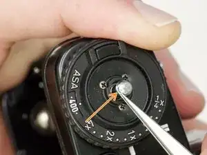
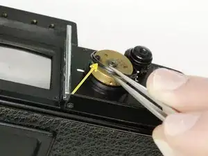
Place a thin tool in the rewind fork and unscrew the topside knob.
-
Remove the washer under the rewind knob.
-
-
-
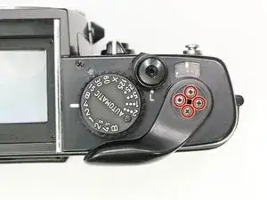
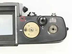
Remove three #000 5.5 mm screws.
-
Remove exposure compensation dial assembly.
-
Remove washer.
-
Remove rubber seal.
-
-
-
Use a piece of tape wrapped sticky side out to grip the winding lever cover.
-
Turn clockwise to loosen and remove
-
Remove four #000 2.5 mm screws.
-
Use spanners to remove top cover retaining nut.
-
-
-
Gently remove the rubber covering around the shutter speed dial.
-
Remove three #000 1.6 mm screws.
-
Remove cover ring.
-
-
-
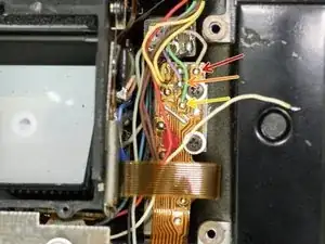
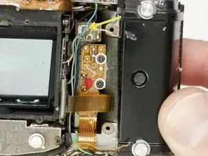
Unsolder one gray wire.
-
Unsolder two yellow wires.
-
Unsolder one blue wire.
-
Unsolder one red wire.
-
-
-
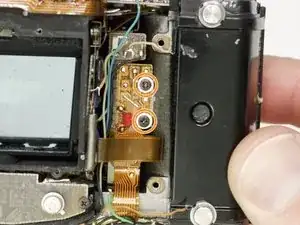
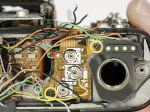
Unscrew four #00 X mm screws.
-
Unsolder one white wire.
-
Unsolder one pink wire.
-
Unsolder one light green wire.
-
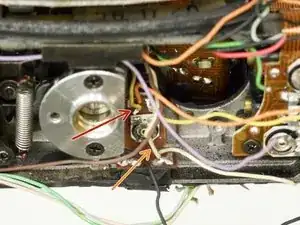
Check the mounting points for shim washers. If they are loose, note the position and remove.
-
-
-
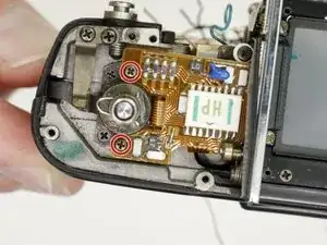
Unsolder one pink wire.
-
Unsolder one purple wire.
-
Unsolder one green wire.
-
Unsolder two yellow wires.
-
Unsolder two brown wires under the loop of flex cable.
-
Unsolder one gray wire.
-
-
-
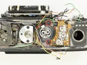
Unscrew three #00 3.0 mm screws.
-
Remove exp/ISO resistor assembly.
-
Remove exp. compensation coupling cam.
-
There are two loose ball bearings that sit in these holes. Do not lose.
-
-
-
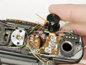
Unsolder five black wires.
-
Unsolder two green wires.
-
Unsolder one purple wire.
-
Unsolder one yellow wire.
-
Unsolder one orange wire.
-
Unsolder one light brown wire.
-
-
-
Unsolder one light blue wire (may appear beige).
-
Unsolder one green wire.
-
Unsolder one pink wire.
-
Unsolder one blue wire.
-
Unsolder two black wires.
-
Unsolder one red wire.
-
Unsolder one brown wire.
-
-
-
Unsolder one yellow wire.
-
Unsolder one white wire.
-
Unsolder one light blue/teal wire.
-
Unsolder one gray wire.
-
-
-
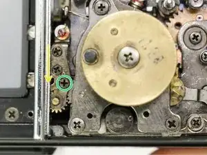
Turn shutter speed selector to 'Auto'.
-
Turn lock lever screw clockwise to loosen. Do not remove.
-
Push lock lever toward the needle indicator gear.
-
Turn lock lever screw counter-clockwise to tighten.
-
-
-
Remove two #00 2.8 mm screws. Remove two loose spacers underneath the PCB.
-
Remove two #00 2.0 mm screws.
-
Remove two #00 2.0 mm screws.
-
-
-
Remove two #00 3.0 mm screws.
-
Remove one #00 5.0 mm screw.
-
Remove mirror box by lifting up then out. Pull slowly and check for snags as you remove.
-


To reassemble your device, follow these instructions in reverse order.