Introduction

Follow this guide to replace the screen and battery assembly on your Samsung Galaxy S23 Ultra.

This guide is written for the screen and battery assembly. The assembly consists of the screen, battery, and frame together in one part. Be sure you have the right part before you begin the repair.

Before disassembling your device, completely discharge the battery. This reduces the risk of a dangerous thermal event if the battery is accidentally damaged during the repair. If your battery is swollen, take appropriate precautions.

Note: Retaining water resistance after the repair will depend on how well you reapply the adhesive, but your device will lose its IP (Ingress Protection) rating.

  1. gNkOBiPPpophUDNr
    • Heat an iOpener and apply it to the right edge of the back cover for two minutes.

    • A hair dryer, heat gun, or hot plate may also be used, but be careful not to overheat the phone—the display and internal battery are susceptible to heat damage.

  2. IuCMlKZJGZi1ZVaC
    IuCMlKZJGZi1ZVaC
    KNAxXgUOFSBnu5Tl
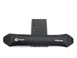
    • While you wait for the adhesive to soften, note the following:

    • There's adhesive securing the back cover around the perimeter of the frame.

    • The adhesive is strongest in the bottom right and top left corners.

  3. vMQmqEcgrXmLtjLt
    vMQmqEcgrXmLtjLt
    xv4POooYFbuFFQaL
    1ew2vBskdRhjA1oc
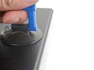
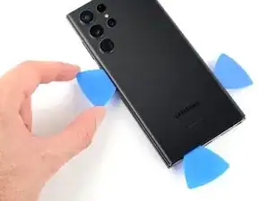
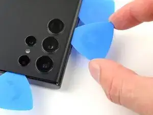
    • Apply a suction handle to the back cover, as close to the center of the right edge as possible.

    • Pull up on the suction handle with strong, steady force to create a gap between the cover and the frame.

    • If you have trouble creating a gap, apply more heat to further soften the adhesive. Follow the iOpener instructions to avoid overheating.

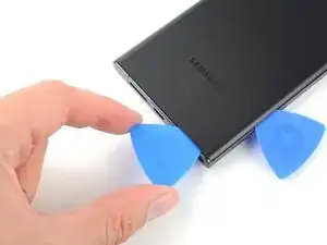
    • Insert an opening pick into the gap.

  4. epeLbFTQBXjV2jZW
    epeLbFTQBXjV2jZW
    m6ugW1SmIVnKgjbL
    JxOIJfnD5MqPsSIZ
    • Slide the pick back and forth along the right edge to separate the adhesive.

    • Leave the pick inserted near the bottom right edge to prevent the adhesive from resealing.

  5. KFdNe44w3fG4TbWI
    • Apply a heated iOpener to the bottom edge of the back cover for two minutes.

  6. EL5XPENpDlhIiOyA
    EL5XPENpDlhIiOyA
    wRhFidJoSdjeGULV
    WUD33WamJEQHTyHI
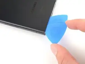
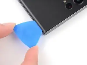
    • Insert a second opening pick at the bottom right corner.

    • Angle the pick upward to match the curved edge and rotate it around the bottom right corner.

    • Be careful while working around the corners, as the glass is very fragile here. Work slowly to avoid cracking the glass.

  7. cty2RNPr1Xsulgpr
    cty2RNPr1Xsulgpr
    nXBxWO6bjwLC6cnM
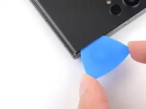
    • Slide your opening pick to the bottom left corner to separate the adhesive.

    • Leave the pick in the bottom left corner to prevent the adhesive from resealing.

  8. IEXDLNdqR3xFYkmP
    • Apply a heated iOpener to the left edge of the back cover for two minutes.

  9. mxXPBGcWiCJfJ3BS
    mxXPBGcWiCJfJ3BS
    olFGEuhIxCIMJcdh
    Arf4HwrTgVSrTFcF
    • Insert a third opening pick at the bottom left corner.

    • Angle the pick upward to match the curved edge and rotate it around the bottom left corner.

    • Be careful while working around the corners, as the glass is very fragile here. Work slowly to avoid cracking the glass.

  10. WQmptomBoBQeKuJX
    WQmptomBoBQeKuJX
    4xUwuDfsngL1cFlA
    lkBfZG4mnYPnx1Sb
    • Slide your opening pick along the left edge to separate the adhesive, stopping when you reach the power button.

    • Only insert the pick up to 5 mm, as you may damage the antenna flex cable or the power button cable.

    • Leave the pick in the left edge to prevent the adhesive from resealing.

  11. YMTlXG5toWQfJoLs
    • Heat an iOpener and apply it to the top edge of the back cover for two minutes.

  12. XfPcTdZECHnXRILb
    XfPcTdZECHnXRILb
    MGUhrVwiAaWJfCKS
    tFFB6IAGHuBb5NvR
    • Insert an opening pick in the gap at the top right edge.

    • Angle the pick upward to match the curved edge and rotate it around the top right corner.

    • Be careful while working around the corners, as the glass is very fragile here. Work slowly to avoid cracking the glass.

  13. AuYJOFYpAYcxqteY
    AuYJOFYpAYcxqteY
    oxPnH3tCjYANEWsu
    • Slide the pick to the top left corner to separate the adhesive.

    • Only insert the pick up to 4 mm, as you may damage the cameras or sensors.

    • Leave the pick in to prevent the adhesive from resealing.

  14. ypnYS5EupERNUwVm
    ypnYS5EupERNUwVm
    GceGlFTsFRUWDKiq
    • Insert an opening pick in the gap at the top left edge.

    • Only insert the pick up to 4 mm, as you may damage the cameras.

    • Angle the pick upward to match the curved edge and rotate it around the top left corner.

  15. NaNGOKtwpRwEUZYI
    NaNGOKtwpRwEUZYI
    RSCerWvIrEVKfxol
    • Slide the pick toward the bottom camera to separate through the remaining adhesive, stopping before you reach the power button.

    • Only insert the pick up to 4 mm, as you may damage the cameras.

  16. emFCoW1YANLRMfkZ
    emFCoW1YANLRMfkZ
    jSwV1tlpdJtaiXwY
    eKODttjYVLjUWKnA
    • Grab and remove the back cover.

    • If your cover is still sticking to the frame, slide an opening pick around the perimeter until the cover completely separates.

    • During reassembly:

    • This is a good point to power on your phone and test all functions before sealing it up. Be sure to power your phone back down completely before you continue working.

    • Remove any adhesive chunks with a pair of tweezers or your fingers. Apply heat if you're having trouble separating the adhesive.

    • If you're using custom-cut adhesives, follow this guide.

    • If you're using double-sided tape, follow this guide.

  17. Mpv2PsbCdI1iW6Wb
    Mpv2PsbCdI1iW6Wb
    oj5xEmMeYhOpTSBr
    qfgottJDieSAVxSq
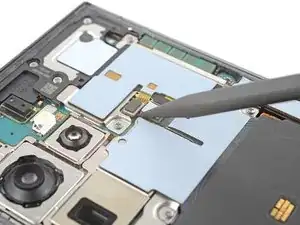
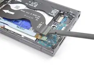
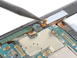
    • Use the pointed end of a spudger to pry up and disconnect the NFC antenna press connector from the motherboard.

    • Repeat for the wireless charging coil press connector.

    • To re-attach press connectors, carefully align and press down on one side until it clicks into place, then repeat on the other side. Don't press down on the middle. If the connector is misaligned, the pins can bend and cause permanent damage.

  18. h5cMIyxpAtqjbKU4
    h5cMIyxpAtqjbKU4
    V4QoZv3VfMBsKpaU
    e3Xe11ICRIVOP6VV
    • The wireless charging coil is lightly adhered to the battery.

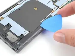
    • Insert an opening pick between the right edge of the wireless charging coil and the battery.

    • Slide the pick along the right edge to separate the adhesive.

  19. YWBGWevJudPUNtxB
    YWBGWevJudPUNtxB
    aN12mHIkZCFnugfP
    • Insert an opening pick between the top edge of the wireless charging coil and the frame.

    • Slide the pick toward the right edge to separate the remaining adhesive.

  20. MqBoxonnnfOluifG
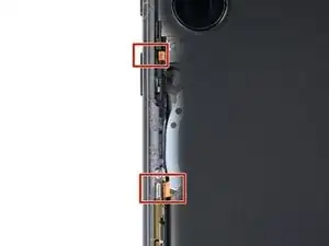
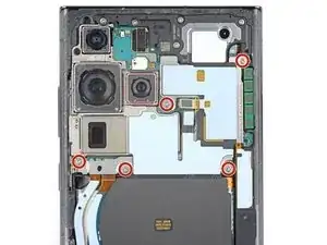
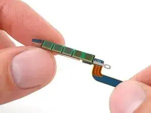
    • Use a Phillips screwdriver to remove the five 3.5 mm-long screws securing the NFC antenna and charging coil.

  21. A5ENg165DhNqsGVf
    • Use a Phillips screwdriver to remove the six 3.5 mm screws securing the loudspeaker.

  22. AUNWPUyerrpSCGAn
    AUNWPUyerrpSCGAn
    O1a6hFfuIO3JDxai
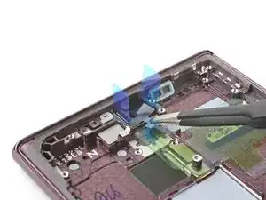
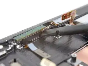
    • Insert the pointed end of your spudger between the upper right corner of the loudspeaker and the frame.

    • Pry up to unclip the loudspeaker from the frame.

    • Don't pry against the battery. Use protrusions in the frame for leverage.

    • During reassembly, press around the perimeter of the loudspeaker to clip it to the frame.

  23. 1FHZvGkxEADnOK2w
    1FHZvGkxEADnOK2w
    kOOFuS1g3BJGNd6D
    jrAtNKEbQKxi4JXe
    • Grab and remove the NFC, wireless charging coil, and loudspeaker from the frame.

  24. WJL6tgiasytMwPG1
    WJL6tgiasytMwPG1
    SZ6JmRc4R2SVgBXV
    • Use your spudger to pry up and disconnect the battery press connector.

  25. XQiBjavuIQwsdbGQ
    XQiBjavuIQwsdbGQ
    yBRBmm1RwXbsnvJp
    iL5GGGZkAg6uPM1t
    • Use your spudger to pry up and disconnect the secondary interconnect cable press connector from the motherboard.

    • Repeat for the primary interconnect cable.

  26. sDYI4flX1KoiTYEb
    sDYI4flX1KoiTYEb
    NpWHNYcSugDSIFPk
    WHpPe2RSPDF1LHlP
    • Use your spudger to pry up and disconnect the secondary interconnect cable press connector from the charging board.

    • Repeat for the primary interconnect cable.

  27. bbHodDhgIPvDNJFN
    bbHodDhgIPvDNJFN
    lLTakaJoqbpmld4v
    • Grab and remove the interconnect cables from the frame.

  28. 2BBA1lIAgFYCuVyS
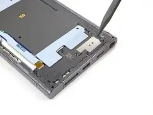
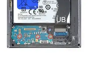
    • Use a Phillips screwdriver to remove the three 3.5 mm-long screws securing the charging board.

  29. ZcLVwMnNkaiZE55o
    ZcLVwMnNkaiZE55o
    iCLwToDSGOsfS6Gi
    4fioUMA3tkH53QJk
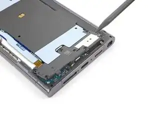
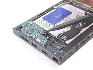
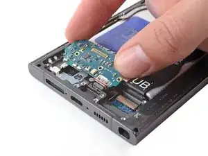
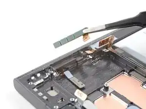
    • Insert the point of your spudger under the top right of the charging board.

    • Pry the charging board up from its recess until you can grab it with your fingers.

    • Pull the charging board toward the top of the device to remove it from its recess.

    • During reassembly, reinsert the charging board at a downward angle to guide the USB-C port into its recess.

  30. vWSZmYttHZFGe1HV
    vWSZmYttHZFGe1HV
    cbVdQqfFKPXNXFER
    • Use the point of your spudger to pry up and disconnect the earpiece speaker press connector.

  31. k4JKLpVUnMhOlJ3C
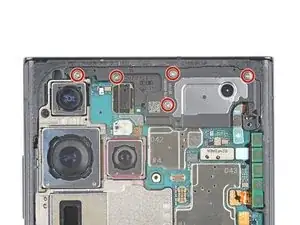
    • Use a Phillips screwdriver to remove the five 3.5 mm-long screws securing the motherboard cover.

  32. eetNiEWZRPt4HTIN
    eetNiEWZRPt4HTIN
    j4ScW61H3AWgVXwP
    Vh3TexCSGwiUux6d
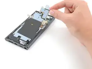
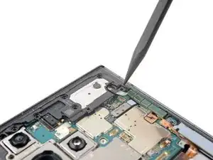
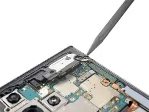
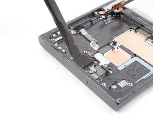
    • Insert the point of your spudger between the bottom right corner of the motherboard cover and the frame.

    • Pry up on the cover to unclip it from the frame.

    • Remove the motherboard cover.

    • During reassembly, press down on the cover to secure its clips to the frame.

  33. NuJYgHVKFUavTcLN
    NuJYgHVKFUavTcLN
    Fp1ArDosmVw2o1Ev
    • Use the point of your spudger to pry up and disconnect the front-facing camera press connector.

  34. kKNUGZCWsqIhe56f
    kKNUGZCWsqIhe56f
    ylDQjNhrRObyvnCo
    • Use your spudger to pry up and disconnect the fingerprint reader press connector.

  35. PIQuIseXNMXJFVRC
    PIQuIseXNMXJFVRC
    nhOTHJMM4MbLenDX
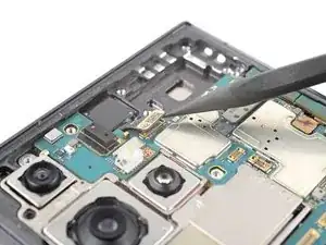
    • Use the point of your spudger to pry up and disconnect the screen press connector from the motherboard.

  36. wsNS5GUIgJ1Hj4nD
    wsNS5GUIgJ1Hj4nD
    I14vO2yAQaYIGLjw
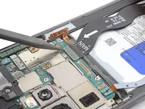
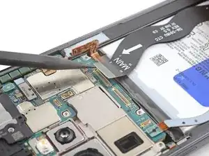
    • Use the point of your spudger to pry up and disconnect the screen press connector near the bottom of the phone.

  37. TK3KClBc5guF14Nr
    • Grab and remove the screen cable from the frame.

  38. xNxqRJvEnipAscaw
    xNxqRJvEnipAscaw
    4YiVHa3akcTc5RvA
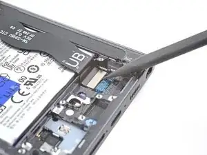
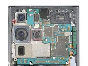
    • Use the point of your spudger to pry up and disconnect the right 5G mmWave antenna press connector.

  39. SQhUDbPZWxCjQmkx
    SQhUDbPZWxCjQmkx
    oEZef5r5eIpyM2fC
    • Use the point of your spudger to pry up and disconnect the stylus press connector.

  40. yJGRKqOMNHBqkYxJ
    yJGRKqOMNHBqkYxJ
    UFqYA1tPLIHfYRuD
    • Use the point of your spudger to pry up and disconnect the left 5G mmWave antenna press connector.

  41. Kub2fThk4fb1ENVS
    • Use your Phillips screwdriver to remove the 4 mm-long screw securing the motherboard.

  42. KuUFxjRQiMNvRiNd
    KuUFxjRQiMNvRiNd
    bs1hD1piGTbOabZf
    E4JEGJHYuWOrBF6R
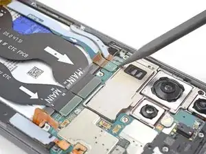
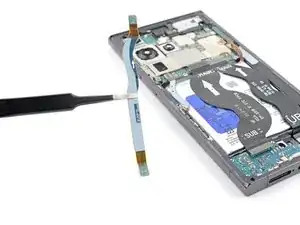
    • Insert the point of your spudger between the top left of the motherboard and the frame.

    • Pry the motherboard up until you can grab it with your fingers.

    • Grab the motherboard and remove it from the frame.

    • Be careful not to catch on any loose cables.

    • During reassembly, be sure the cables are above the motherboard when reinserting it.

  43. TBssiGLOPXSRxlKM
    • Heat an iOpener and apply it to the top of the screen for two minutes.

    • A hair dryer, heat gun, or hot plate may also be used, but be careful not to overheat the phone—the display is susceptible to heat damage.

  44. X2raiPLaifIDlEGD
    X2raiPLaifIDlEGD
    6dNVX5oR2KMpM5Sv
    HsaWocXQi5gMXxWh
    • The adhesive securing the camera is very strong. Work slowly and apply more heat if the camera feels stuck. Avoid separating the circuit board from camera housing, such as this.

    • Use the flat end of your spudger to pry the front-facing camera from its recess.

    • If the camera doesn't loosen, use your SIM card eject tool to scrape away the epoxy surrounding the camera.

  45. MBFAZSbr6DDhCO5V
    MBFAZSbr6DDhCO5V
    6Z3NVXwadMXBOoXI
    • During reassembly, prepare your new frame for the front-facing camera:

    • Remove the black adhesive liner from the front-facing camera recess.

    • Peel and remove the foam liner from the new frame.

    • This liner isn't necessary for the repair.

  46. BV2JtEMPMxJerHNY
    BV2JtEMPMxJerHNY
    CwYG4RvAASFv2tqT
    AvqQ5nhWjy13K3Vo
    • Before installing the front-facing camera in your new frame, apply new adhesives onto the frame and the camera:

    • Remove the two large clear rectangular liners from the adhesive sheet and place the adhesives on the sides of the camera recess.

    • Remove the liner from the main adhesive piece and place it in the center of the camera recess with its pull tab facing the bottom of the frame.

    • Remove any adhesive residue from the front-facing camera module.

    • Remove the liner from the thin piece of adhesive and place it on the top edge of the camera.

  47. ZK3VLrsdECBvlt5y
    ZK3VLrsdECBvlt5y
    njtLpFGRFkwyi2jE
    • Install the front-facing camera:

    • Remove all four blue adhesive liners from the camera and the frame.

    • Insert the front-facing camera into its recess in the frame and apply pressure to secure it.

  48. 5TiMKpNUKWoyc4VB
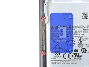
    • Use a Phillips driver to remove the two 2.4 mm‑long screws securing the left 5G mmWave antenna.

  49. ZuZvJPyTdf2QS1u5
    ZuZvJPyTdf2QS1u5
    QRdEYMUCVMSjVQSn
    DxpNSsViFZExCMKR
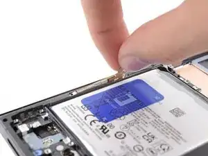
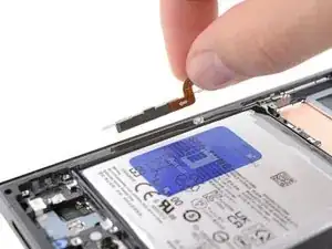
    • Grab the left 5G mmWave antenna connector and lift up to separate the bracket from the frame.

    • Remove the antenna.

  50. BgKHBIVEhCVEkCuI
    BgKHBIVEhCVEkCuI
    R5Ac3TXWIY5lMTZp
    WGBEPRFeDe5xO2wU
    • Before reinstalling the lower 5G mmWave antenna, replace the bracket with a new one. If you don't have a new bracket, skip this step.

    • Remove the antenna and connector from the old bracket.

    • Remove the L-shaped adhesive liner from your new bracket.

    • Place the antenna in the bracket's recess with the connector fed underneath the longer screw mount.

    • Remove the thin adhesive liner on the outside of the bracket before installing it in the frame.

  51. aQ5VbOMYwHy5ZUvC
    aQ5VbOMYwHy5ZUvC
    ApY4AaEbmTHo4IBS
    QTd4UQMG1FqcsHWP
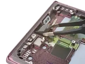
    • Insert the flat end of a spudger between the frame and the right 5G mmWave antenna connector.

    • Pry up with the spudger to separate the adhesive.

  52. SgybD2BLXeJbYdAJ
    SgybD2BLXeJbYdAJ
    SmGShFS2KeZUmcd4
    • Grab and remove the right 5G mmWave antenna from the frame.

  53. LTV4INO3ruKtcCXq
    LTV4INO3ruKtcCXq
    jnIS3Fr2IeLheerF
    oKKsotUTKKr2ATlV
    • Replace the adhesive on the upper 5G mmWave antenna before reinstalling it. If you don't have replacement adhesive, reuse your old one or use custom-cut adhesive.

    • Remove the existing adhesive from the antenna with blunt nose tweezers or your fingers.

    • Remove the clear liner from your new adhesive.

    • Apply the new adhesive to the bottom of the antenna, with its round end farthest from the connector.

    • Remove the green liner from the adhesive before reinstalling the antenna in the frame.

  54. jMiRQISXkSSS44Lo
    • You're now left with the screen and battery assembly.

    • Compare your new replacement part to the original part—you may need to transfer remaining components or remove adhesive backings from the new part before you install it.

Conclusion

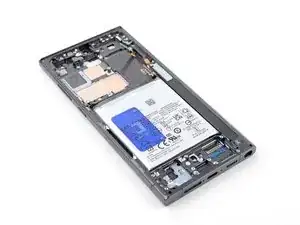
To reassemble your device, follow these instructions in reverse order.

Take your e-waste to an R2 or e-Stewards certified recycler.

Repair didn’t go as planned? Check out our Answers community for troubleshooting help.

Alex Diaz-Kokaisl

Member since: 16/01/22

127411 Reputation

One comment

Can you share a propper way to change the screen

Muzakkir -