Introduction

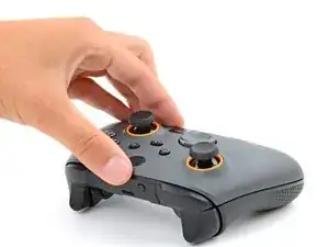
Follow this guide to replace, change, or upgrade, a single trigger, or both triggers (LT and RT), on your Scuf Instinct Pro Xbox controller.

The triggers are also called trigger covers or LT and RT covers.

  1. 5OkDhPDMtblly2hJ
    5OkDhPDMtblly2hJ
    XWguLyDlcAWJXAwe
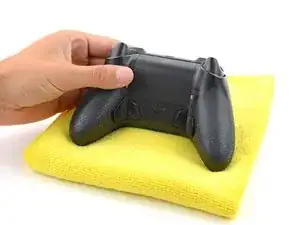
    • Unplug all cables from your controller before starting.

    • Completely power off your controller.

    • Due to the controller’s odd shape, it can be helpful to stabilize it as you work. To prevent damage, consider laying it on a soft surface like a cloth or towel.

  2. grHqonDk3VFuVbNF
    grHqonDk3VFuVbNF
    wouLFNuxACh2S1Wf
    n2PXvosWOaAsS5gZ
    • Magnets secure the faceplace to the midframe.

    • Lift the top edge of the faceplate to release the magnets securing it.

    • Remove the faceplate.

  3. hyRWWXIRLvrHuSQL
    hyRWWXIRLvrHuSQL
    ZbCNDRrCGhoiIVGC
    • Weak magnets and two clips along the bottom edge secure the battery cover to the controller.

    • Slide the battery cover away from the controller to remove it.

  4. anhICJF3JAFjokMG
    anhICJF3JAFjokMG
    uYrpCINQBCVJSqBJ
    wdMWQabbNBOVNiEF
    • If your batteries are starting to corrode, clean the contacts and replace the batteries.

    • Use your fingers to remove the batteries.

    • During reassembly, insert the batteries so their positive (+) and negative () ends match up with the markings on the battery contacts.

  5. nAbqyikSyoGLOIrb
    nAbqyikSyoGLOIrb
    DcIHNSrbj1pCoUam
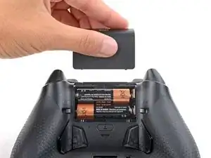
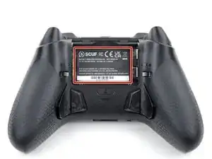
    • The sticker in the battery recess hides a back cover screw.

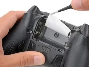
    • If you don't care about damaging the sticker, you can puncture through the center and skip the next step.

    • Use a hair dryer to heat the sticker and soften the adhesive securing it.

    • The sticker can be peeled without heating, but you risk tearing it.

  6. OGWoOKOuU32v2hXb
    OGWoOKOuU32v2hXb
    I3E5ejKIfqYVh5qH
    egxoVafpcqmojEou
    • Use the point of a spudger to push up a corner of the sticker until you can grab it with a pair of blunt nose tweezers.

    • Use your tweezers to peel up the sticker until the back cover screw is accessible.

  7. usZ6GVsD4ZmmZEy1
    usZ6GVsD4ZmmZEy1
    SGMgj5NljxikbFQh
    vMbY1KF1sp5gCrZq
    • Throughout this repair, keep track of each screw and make sure it goes back exactly where it came from.

    • Use a T8 Torx screwdriver to remove five 9.3 mm‑long screws securing the midframe:

    • One back cover screw

    • Four screws on top of the midframe

    • Use a T6 Torx screwdriver to remove the two 9.3 mm‑long screws securing the midframe.

  8. 1OZXAgc3nXRBdfXa
    1OZXAgc3nXRBdfXa
    CxHYPQSdD6EIIFjY
    1gLapEMOHCJHEJhi
    • Plastic clips secure the bottom edge of the midframe.

    • Insert the flat end of a spudger between the bottom edge of the midframe and back cover.

    • Pry the midframe up with the spudger to release the clips.

    • Continue prying along the bottom edge to release the remaining clips.

    • Don't try to remove the midframe from the back cover yet—a delicate ribbon cable connects them.

  9. Z3AirmDZVD2SgSqj
    Z3AirmDZVD2SgSqj
    ZSLPuvcLVL4rvBdR
    UmxecefAqNFAwQnE
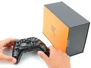
    • Put a box or a stack of books to the right of the controller so you can prop up the midframe while disconnecting its ribbon cable.

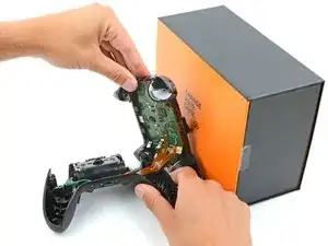
    • Secure the back cover with one hand, and use your other hand to grip the midframe's left edge.

    • Lift the midframe and rotate it over the right edge of the back cover, so the midframe's right edge is on your workspace.

    • Prop the midframe up, being careful not to strain the ribbon cable.

  10. 1vQiclLYfQdj2Io6
    1vQiclLYfQdj2Io6
    PnQZZO1B3CCQYjqI
    urnvPfTZR1VSESyY
    • During reassembly:

    • Guide the battery connectors on the midframe through their slot in the back cover.

    • Make sure the contacts slide into their grooves in the battery recess. If they aren't in the correct spot, the controller won't receive power.

  11. myeAySa4KWvoPjIX
    myeAySa4KWvoPjIX
    ihvxVtTbecGDLqSi
    FBB2mYjV2LT6yRcS
    • A very small rubber grommet secures the midframe's ribbon cable to a post on the right side of the back cover.

    • Use blunt nose tweezers to remove the grommet—don't lose it!

  12. Qa1erEUClJCRsF56
    Qa1erEUClJCRsF56
    5XicudyuHHBQ1vZw
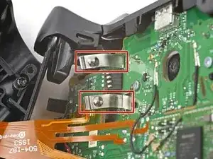
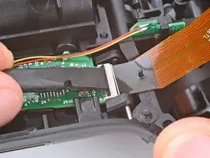
    • Use the flat end of a spudger or a clean fingernail to lift the hinged locking flap on the midframe cable ZIF connector.

  13. Trp325IdcEqi2uoD
    Trp325IdcEqi2uoD
    yvfmQNMlSUkQcQqZ
    vW31enFIv3v3wCPl
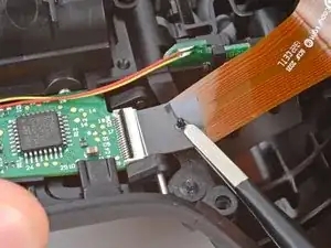
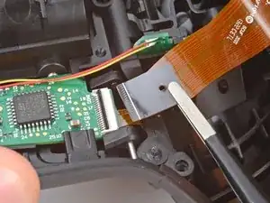
    • Use blunt nose tweezers to grip the black pull tab on the midframe cable.

    • Lift the midframe cable off its post and pull it straight out of its socket.

  14. fDufFLpIndrjKXDy
    • Remove the midframe.

  15. 3xVhRLMjIdnCc3mC
    3xVhRLMjIdnCc3mC
    3IgDnMRcFg3cAHJL
    QxMXH2dkSHQCwneF
    • The top of the USB‑C port cover is secured with a pair of plastic arms. The bottom is secured with plastic clips.

    • Rotate the underside of the USB‑C port cover up and away from the controller to release the bottom clips.

    • Unhook the plastic arms and remove the cover.

    • During reassembly:

    • Hook the ends of the USB‑C cover's arms into their slots on either side of the Xbox button.

    • Rotate the cover downward until the bottom clips engage and the cover is flush with the bumpers.

  16. SMjhwXlTIMKdtnCY
    SMjhwXlTIMKdtnCY
    xInj6IUjnlXxOHEi
    fometAhhd3K4LwoL
    • Tight plastic clips secure the outer edges of the bumpers. Unclipping them requires some force.

    • Insert the point of a spudger between the midframe and the inner edge of one of the clips.

    • Pry the clip outward until it comes off its post and the bumper is freed.

  17. 5LdHnsFsoToxf1AK
    5LdHnsFsoToxf1AK
    KEZrkQNDjaG12wDy
    g1scHKTHykRBR5vK
    • Use your fingers to rotate the other bumper away from the controller until the clip comes off its post.

    • Remove the bumpers.

    • During reassembly:

    • Make sure the tabs on the midframe and bumpers go into their corresponding cutouts.

    • Hook one of the bumpers onto its post and push the other bumper into the midframe until its clip snaps into place.

  18. tdgPaEHMVWV6EEho
    tdgPaEHMVWV6EEho
    OSDBJ2vsP2pHP3Rp
    HehY4cjqGkQJrMBg
    • Use a T6 Torx screwdriver to remove the 7 mm‑long screw securing each trigger (two total).

  19. fEIjMBd3nDDjp3o6
    fEIjMBd3nDDjp3o6
    UdyscX3CdPNIM4l3
    ThkWWJgxWukBoJWe
    • A clip secures the inside edge of the trigger.

    • Rotate the trigger toward the center of the controller to unclip it.

    • Remove the trigger.

  20. PpbEyvINT5YWHhHF
    PpbEyvINT5YWHhHF
    p1GoG333nsFr24oG
    5ZhjaOOynUUjTDDf
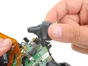
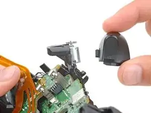
    • Use the same process to remove the other trigger.

    • During reassembly:

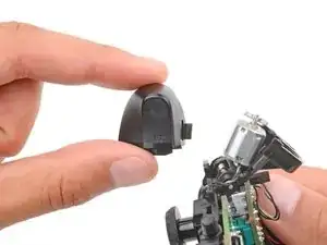
    • Make sure the trigger rumble motors are correctly oriented (flat-side up) before installing a trigger.

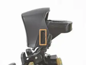
    • To install a trigger, hook the inside edge onto its post and push the trigger until it snaps into place.

Conclusion

To reassemble your device, follow these instructions in reverse order.

Take your e-waste to an R2 or e-Stewards certified recycler.

Repair didn’t go as planned? Try some basic troubleshooting, or ask our Answers community for help.

Spencer Day

Member since: 14/09/22

59589 Reputation

0 comments