Introduction
If your Voluas VL001 pet feeder is having problems with portion control, you may have an issue with your portion switch. The portion switch is a small electronic switch that gets activated as the main drive gear turns, letting the motherboard know how much food was dispensed.
This replacement requires special skills like wire stripping and soldering.
-
-
Remove the lid to the storage tank by using the latch and lifting off.
-
Grab the food storage tank on both sides. Depress the tabs that say "Push" on them and lift the tank off.
-
-
-
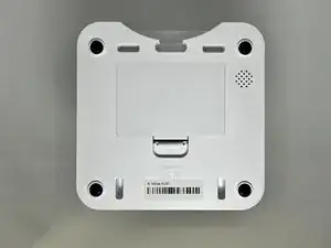
Place your pet feeder upside down.
-
Squeeze the lock and remove the battery cover.
-
Remove the three 1.5V D alkaline batteries.
-
-
-
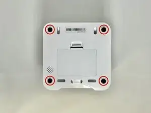
Remove four screws from the corners of the device using a Phillips #2 screwdriver.
-
Using the magnetic tip of the screwdriver, carefully lift the screw out of the hole.
-
-
-
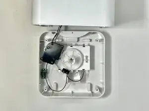
Turn the device over so it is oriented right-side up.
-
Lift the top part of the feeder off, exposing the mechanisms that run the feeder.
-
-
-
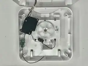
Remove the two 11.1 mm screws that secure the switch to the device using a Phillips #2 screwdriver.
-
-
-
Using your wire strippers/pliers, gently crimp the plastic insulation on the wire. Do this several times around the wire to make sure that you can pull it off.
-
You will want to see a score line in the insulation all around the wire like this.
-
Pull the end of the insulation off, exposing the wire.
-
-
-
Put the exposed wire on the solder patch, making sure it has good contact with the metal.
-
Solder the wire on to the solder patch.
-
Repeat steps 8 and 9 for the other two wires.
-


To reassemble your device, follow these instructions in reverse order.