
Introduction
This guide will show you how to replace the joystick on your Xbox Series X Wireless Controller (Model 1914) and fix stick drift.
Note: This guide requires soldering. For more information on soldering take a look at this guide for How to Solder and Desolder Connections.
Caution: The soldering iron gets very hot and can cause injury.
Note: It is also important to solder in a well-ventilated room.
-
-
Have everything you will need on-hand at your workspace. This includes:
-
Your tools:
-
A Torx screwdriver with a T8 sized head (2.31mm) and a T6 sized head (1.70mm)
-
A soldering rod and solder
-
Spudger
-
Tweezers (optional)
-
The replacement joysticks
-
A clean, uncluttered place to work and keep your screws organized.
-
-
-
Start by flipping the controller over and opening the battery compartment located on the middle back of the controller.
-
Remove the batteries and place both the cover and the batteries off to the side for now.
-
-
-
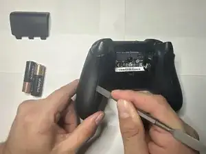
Next, take your opening tool and pry off the grip plates.
-
Using your opening tool, insert it into the grove found on the back of the grips.
-
Slide the tool throughout the groove, prying in the spots that you feel the most resistance until it comes free.
-
Repeat this until the grip cover comes off.
-
Do the same for the other grip.
-
-
-
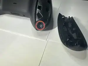
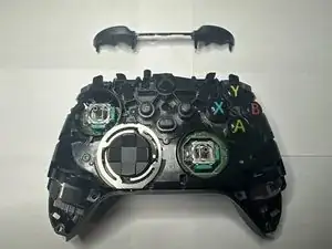
After removing the grip plates, remove the 5 screws holding the front plate.
-
The screws are shown in the picture, two in each grip and one in the battery bay.
-
-
-
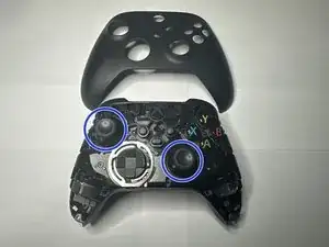
After removing the back screws, the face plate should be easy to remove. Remove it and place it to the side for later.
-
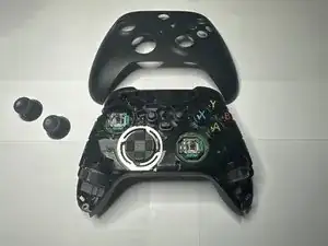
Next, locate the joysticks covers and remove them by simply pulling them up from the controller.
-
Place the joysticks off to the side.
-
-
-
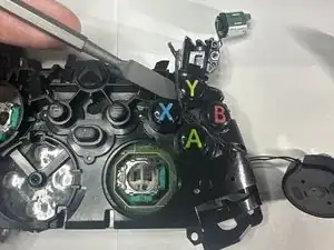
Next is the sync button plate.
-
Place your spudger as shown and gently peel the plate off using the same method as before.
-
Remove the sync plate and place it off to the side for later.
-
-
-
After that, locate the RB and LB bumper piece and, using your metal spudger, place it between the frame and the hinge.
-
Gently pry the piece away and off, doing the same for the other end of the bumper piece.
-
Having done this successfully, the bumper piece should come off cleanly and with little effort.
-
Set the bumper piece off to the side.
-
-
-
By now, the back plastic frame should simply fall off the main components.
-
Take the back piece off and leave it off to the side for now.
-
-
-
Take the main piece and flip it over to show the main components.
-
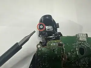
Next, we will be removing both triggers.
-
Move the triggers forward and expose the back parts of the trigger.
-
Using the T6 sized bit, remove the screw from the trigger and place it safely off to the side.
-
Do the same for the other trigger and set the pieces off to the side.
-
-
-
With the trigger frames out of the way, remove the trigger weights from the triggers and place them out of the way.
-
-
-
Next, we will disconnect the wires for the select and menu buttons.
-
Using either your fingers or a set of tweezers, gently pull the connection up and away to disconnect it.
-
Do this for both connections.
-
While here, remove the two screws above the connections. These connect the motherboard to the frame.
-
-
-
Next is the grip rumble weights.
-
Simply, using your hands or forceps, remove the weights by sliding them towards you and lifting them out.
-
-
-
With both set of rumble weights out of the way, next is the board screws.
-
Using the T6 bit screwdriver, unscrew the screws located on next to where the grip rumble weights were.
-
Set these screws aside for now.
-
-
-
Flip the controller over.
-
Following the cord attached to the trigger it should be attached to the controller via small tracks.
-
Gently pull the wire out from the tracks and lay the wire and trigger parts out of the way.
-
-
-
Find the D-pad plate surrounding the outer rim of the D-pad.
-
Using your spudger, slide it underneath the piece and pull it up from the controller.
-
Remove the plate and set it to the side.
-
Taking off the plate should free the plastic D-pad. Remove it from the controller and place both the plate and cover to the side for now.
-
-
-
After flipping over the controller, isolate the loose motherboard, the one with the joysticks attached.
-
Lay the board flat and observe for any debris or clear obstructions.
-
-
-
Flip the board over.
-
Locate the joystick solder nubs on the back of the bottom of the board.
-
Using the soldering iron, heat it up to around 350-375 degrees Fahrenheit, and then lay the tip on the aforementioned nubs.
-
Hold it for around 5-7 seconds or until the solder nub liquefies. Repeat this for the rest of the nubs.
-
Having done this, the joystick should slide out the board. Install the replacement joystick by sliding in the joystick prongs into the slots that the old joystick sat in.
-
With the joystick in, solder the prongs until they are secured into place on the boards.
-


To reassemble your device, follow these instructions in reverse order.
