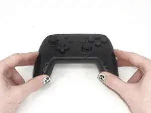
Introduction

The ABXY buttons are important because they are the primary method of controlling inputs to a game or menu. These buttons are easy to take out after taking off the front cover, so they are popular to customize and modify. If you are experiencing ABXY buttons that stick or are unresponsive, it may be time to clean or replace them.

In replacing the ABXY buttons, you will need a Phillips #1 screwdriver, an opening pick, and a pair of tweezers.

If the ABXY buttons (A, B, X, Y, D-Pad, +, –, HOME, and Screenshot buttons) on your YCCTEAM YCC-SW4001 have debris under them, are broken, or are not functioning properly, you can follow this guide to clean or replace them.

  1. ngdvO1ZITkwfT1R2
    • Use a Phillips #1 screwdriver to remove the eight 9.15 mm screws that secure the back case.

  2. 6tTL32ZcQEW1lDXR
    6tTL32ZcQEW1lDXR
    jERbIGopXQnXRfnJ
    LfSm3TgWyVSFIJgt
    • Use an opening pick to pry the back cover off of the controller.

    • This exposes the battery’s housing.

  3. Il2gdVMC5L1wHZsk
    • Use a Phillips #1 screwdriver to remove the three 9.15 mm screws from the back of the controller.

  4. nODc5iMbW3gCCqFM
    nODc5iMbW3gCCqFM
    1A5lNfOsdeR15ACA
    NyVsbNoueFmUlM4Y
    • Delicately lift the front case slightly by pulling it away from the back case.

    • Do not remove the front cover completely; it is still attached to the motherboard by a white ribbon cable.

  5. PtvsNhcDONldYhtf
    PtvsNhcDONldYhtf
    6EenHVPCcqYLui5I
    HX1CwAKd6HkVIqYv
    • Use the tip of the opening pick to flip up the black locking flap of the ZIF connector.

    • The black flap holds the white ribbon cable in place.

  6. usdRBfUwDZKPH6Jo
    usdRBfUwDZKPH6Jo
    NHKOphBIgYJLgLmk
    • Use tweezers to disconnect the white ribbon cable from the ZIF connector.

  7. LMoGY2poIJsYn6qa
    • Remove the front case.

  8. tKnt1vLSAWSVmUn1
    tKnt1vLSAWSVmUn1
    5mojWVk4UHICtgqF
    TXcyFPbeoob2PvSY
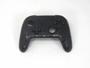
    • Isolate the front cover.

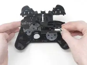
    • Flip over the front cover and remove the four 5.77 mm screws from the back of the front cover using the Phillips #1 Screwdriver.

  9. 5VKJhxFpIGSRWKcg
    5VKJhxFpIGSRWKcg
    YPsJAo2tsUiGMQCF
    4xcMyUaO2eBBfIVV
    • Lift the circuit board from the front cover to expose the back of the buttons.

  10. tEgEoQHvgoCFy1El
    tEgEoQHvgoCFy1El
    yTLUYhy5CiSSvHTZ
    pPNx5AOrrFIoTGSj
    • Remove the rubber caps and the button caps by either dumping them out or taking them out by hand.

Conclusion

To reassemble your device, follow these instructions in reverse order.

Sam Borwick

Member since: 16/02/24

315 Reputation

0 comments