Introduction

If the joysticks on the YCCTEAM YCC-SW4001 are drifting or otherwise not functioning properly, follow this guide to replace them.

The joysticks are the users main form of navigation through a game or a menu. The caps are easy to replace, so it is common to customize the color or shape of the joystick.

One common problem is drifting, which happens after gradual wear and tear. This could be from decay of the joystick caps or the joystick module (the stick under the caps). If the problem lies in the joystick module, replacing this requires knowledge of soldering as well as access to a soldering kit.

  1. ngdvO1ZITkwfT1R2
    • Use a Phillips #1 screwdriver to remove the eight 9.15 mm screws that secure the back case.

  2. 6tTL32ZcQEW1lDXR
    6tTL32ZcQEW1lDXR
    jERbIGopXQnXRfnJ
    LfSm3TgWyVSFIJgt
    • Use an opening pick to pry the back cover off of the controller.

    • This exposes the battery’s housing.

  3. Il2gdVMC5L1wHZsk
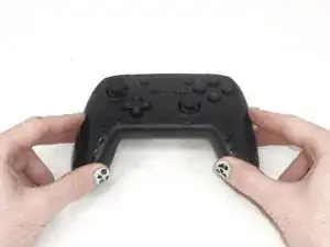
    • Use a Phillips #1 screwdriver to remove the three 9.15 mm screws from the back of the controller.

  4. nODc5iMbW3gCCqFM
    nODc5iMbW3gCCqFM
    1A5lNfOsdeR15ACA
    NyVsbNoueFmUlM4Y
    • Delicately lift the front case slightly by pulling it away from the back case.

    • Do not remove the front cover completely; it is still attached to the motherboard by a white ribbon cable.

  5. PtvsNhcDONldYhtf
    PtvsNhcDONldYhtf
    6EenHVPCcqYLui5I
    HX1CwAKd6HkVIqYv
    • Use the tip of the opening pick to flip up the black locking flap of the ZIF connector.

    • The black flap holds the white ribbon cable in place.

  6. usdRBfUwDZKPH6Jo
    usdRBfUwDZKPH6Jo
    NHKOphBIgYJLgLmk
    • Use tweezers to disconnect the white ribbon cable from the ZIF connector.

  7. LMoGY2poIJsYn6qa
    • Remove the front case.

  8. VIa6GKBHIPCgaFKD
    VIa6GKBHIPCgaFKD
    UZGLYgcoNAlJwuDO
    vavYbgGptYbaQN4a
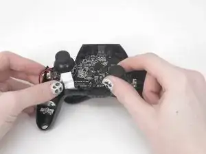
    • Remove the two joystick caps from the circuit board by gripping them and pulling them straight upward with moderate force.

  9. boZJBR3cCRLhEfXL
    boZJBR3cCRLhEfXL
    2qrPCZGZFqmkPFY1
    KjwfnJmlsOs2gYUO
    • Use tweezers to lift the battery connector directly up and out of its motherboard port.

  10. VKdsUbrrmPL4CQ3P
    VKdsUbrrmPL4CQ3P
    lMuaqyDMnlkFeVSF
    jogZHYvZnrp1suP2
    • Use a Phillips #0 screwdriver to remove the three 7.5 mm screws that secure the motherboard.

    • Remove the player LEDs.

  11. 3qyrW1HbQGlEtCRJ
    3qyrW1HbQGlEtCRJ
    IkJQTjUVAgR5rRva
    vQBu2UPjcqMackXD
    • Grip the white rumble motor motherboard connections and pull them directly out of their ports.

    • When replacing the rumble motors, press each plug down into its socket until it snaps into place.

  12. FygmiEVeWavwSfBt
    FygmiEVeWavwSfBt
    HXdJ2VimBcyeLQvo
    • Lift the motherboard out of the controller.

  13. TOfEnJKRNabf3cGr
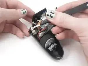
    • To remove each joystick module, desolder the marked connections using a soldering iron and solder wick.

    • Check out this guide to learn the soldering basics.

Conclusion

To reassemble your device, follow these instructions in reverse order.

David Adaway

Member since: 16/02/24

531 Reputation

0 comments