Introduction
This is a tear-down of my very first PDA. The Sony Clie PEG-SJ20. A PDA I used so little, yet carried so much that I now conclude that the only reason I bought it was to look cool. There once was a time when it was cool to carry a cell phone, mp3 player, digital organizer, and pager. (Well, maybe not the pager, but by golly if I did know some hip hop buddies who had two or three of them.) The following is done with much excitement because this is probably the only purposeful thing I have ever done with this device.
-
-
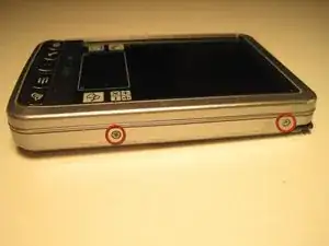
The first thing you will want to do to tear this mother down will be to remove the 6 screws around the three sides of the unit. This requires the #0 Phillips screwdriver.
-
-
-
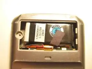
The next thing you'll want to do is remove the battery compartment screw. No need to take the battery out yet. That little bugger comes out easier after the outer frame comes off.
-
-
-
So separating the frame from the internals is fairly obvious. Just pull the thing apart and everything comes out in three pieces. Make sure to remove the stylus before pulling it apart.
-
-
-
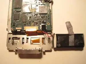
This part of the tear-down proved to be the most frustrating. BE AWARE THAT THE 5 SCREWS CIRCLED WERE EXTREMELY TIGHT! I actually stripped out my cheapo #0 Phillips screwdriver. These 5 screws must be removed to separate the screen from the circuit-board. At this junction I think I am supposed to reveal the technical aspect of what I have found on the circuit board. Unfortunately I see nothing remarkable. There is a Dragonball processor as promised but I have no way of knowing its speed. Supposedly it is a 33mhz processor.
-
-
-
Next, remove the battery. Simply find the red and black wires where they meet the connector on the circuit board. Remove the black tape, grasp the connector near the wires and pull. Easy enough.
-
-
-
The next step involves separating all of the various ribbon wires from the screen and circuit board. There are 5. The first wire is the ribbon wire that connects the memory card to the circuit board. I pulled it out with my screwdriver like shown but I am sure that black piece of plastic piece could have been moved to release the wire from the connectors mighty grip.
-
-
-
Next I removed the wide ribbon that connects the interface to the circuit board. Lifting up on either side of the connectors two white tabs releases the ribbon.
-
-
-
Next, use your screwdriver to lift up on the connectors that connect the scroll wheel to the circuit board. Then pull out the ribbon.
-
-
-
Next, flip the board over so you can see the back side. There should be 3 ribbons attached to the circuit board. (In the picture the white one was not attached as it easily came out when I flipped the board over.) Remove these ribbons from their connectors by simply pulling them out. The circuit board should fully separate from the frame holding the screen now.
-
-
-
Removing the screen from the frame was as simple as could be. I simple pulled it out as it had no fasteners to hold it in.
-
In closing the final tear-down should take you less than 15 minutes. There appeared to be no extra features hidden in the unit. No extra fm radio, bluetooth module, or easter eggs. Overall the innards of this unit are pretty underwhelming.
-