27

Let's say I have a data structure like the following:

Camera {
   double x, y, z

   /** ideally the camera angle is positioned to aim at the 0,0,0 point */
   double angleX, angleY, angleZ;
}

SomePointIn3DSpace {
   double x, y, z
}

ScreenData {
   /** Convert from some point 3d space to 2d space, end up with x, y */
   int x_screenPositionOfPt, y_screenPositionOfPt

   double zFar = 100;

   int width=640, height=480
}

...

Without screen clipping or much of anything else, how would I calculate the screen x,y position of some point given some 3d point in space. I want to project that 3d point onto the 2d screen.

Camera.x = 0
Camera.y = 10;
Camera.z = -10;


/** ideally, I want the camera to point at the ground at 3d space 0,0,0 */
Camera.angleX = ???;
Camera.angleY = ????
Camera.angleZ = ????;

SomePointIn3DSpace.x = 5;
SomePointIn3DSpace.y = 5;
SomePointIn3DSpace.z = 5;

ScreenData.x and y is the screen x position of the 3d point in space. How do I calculate those values?

I could possibly use the equations found here, but I don't understand how the screen width/height comes into play. Also, I don't understand in the wiki entry what is the viewer's position vers the camera position.

http://en.wikipedia.org/wiki/3D_projection

Berlin Brown
  • 11,504
  • 37
  • 135
  • 203

8 Answers8

54

The 'way it's done' is to use homogenous transformations and coordinates. You take a point in space and:

  • Position it relative to the camera using the model matrix.
  • Project it either orthographically or in perspective using the projection matrix.
  • Apply the viewport trnasformation to place it on the screen.

This gets pretty vague, but I'll try and cover the important bits and leave some of it to you. I assume you understand the basics of matrix math :).

Homogenous Vectors, Points, Transformations

In 3D, a homogenous point would be a column matrix of the form [x, y, z, 1]. The final component is 'w', a scaling factor, which for vectors is 0: this has the effect that you can't translate vectors, which is mathematically correct. We won't go there, we're talking points.

Homogenous transformations are 4x4 matrices, used because they allow translation to be represented as a matrix multiplication, rather than an addition, which is nice and quick for your videocard. Also convenient because we can represent successive transformations by multiplying them together. We apply transformations to points by performing transformation * point.

There are 3 primary homogeneous transformations:

There are others, notably the 'look at' transformation, which are worth exploring. However, I just wanted to give a brief list and a few links. Successive application of moving, scaling and rotating applied to points is collectively the model transformation matrix, and places them in the scene, relative to the camera. It's important to realise what we're doing is akin to moving objects around the camera, not the other way around.

Orthographic and Perspective

To transform from world coordinates into screen coordinates, you would first use a projection matrix, which commonly, come in two flavors:

  • Orthographic, commonly used for 2D and CAD.
  • Perspective, good for games and 3D environments.

An orthographic projection matrix is constructed as follows:

An orthographic projection matrix, courtesy of Wikipedia.

Where parameters include:

  • Top: The Y coordinate of the top edge of visible space.
  • Bottom: The Y coordinate of the bottom edge of the visible space.
  • Left: The X coordinate of the left edge of the visible space.
  • Right: The X coordinate of the right edge of the visible space.

I think that's pretty simple. What you establish is an area of space that is going to appear on the screen, which you can clip against. It's simple here, because the area of space visible is a rectangle. Clipping in perspective is more complicated because the area which appears on screen or the viewing volume, is a frustrum.

If you're having a hard time with the wikipedia on perspective projection, Here's the code to build a suitable matrix, courtesy of geeks3D

void BuildPerspProjMat(float *m, float fov, float aspect,
float znear, float zfar)
{
  float xymax = znear * tan(fov * PI_OVER_360);
  float ymin = -xymax;
  float xmin = -xymax;

  float width = xymax - xmin;
  float height = xymax - ymin;

  float depth = zfar - znear;
  float q = -(zfar + znear) / depth;
  float qn = -2 * (zfar * znear) / depth;

  float w = 2 * znear / width;
  w = w / aspect;
  float h = 2 * znear / height;

  m[0]  = w;
  m[1]  = 0;
  m[2]  = 0;
  m[3]  = 0;

  m[4]  = 0;
  m[5]  = h;
  m[6]  = 0;
  m[7]  = 0;

  m[8]  = 0;
  m[9]  = 0;
  m[10] = q;
  m[11] = -1;

  m[12] = 0;
  m[13] = 0;
  m[14] = qn;
  m[15] = 0;
}

Variables are:

  • fov: Field of view, pi/4 radians is a good value.
  • aspect: Ratio of height to width.
  • znear, zfar: used for clipping, I'll ignore these.

and the matrix generated is column major, indexed as follows in the above code:

0   4   8  12
1   5   9  13
2   6  10  14
3   7  11  15

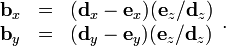
Viewport Transformation, Screen Coordinates

Both of these transformations require another matrix matrix to put things in screen coordinates, called the viewport transformation. That's described here, I won't cover it (it's dead simple).

Thus, for a point p, we would:

  • Perform model transformation matrix * p, resulting in pm.
  • Perform projection matrix * pm, resulting in pp.
  • Clipping pp against the viewing volume.
  • Perform viewport transformation matrix * pp, resulting is ps: point on screen.

Summary

I hope that covers most of it. There are holes in the above and it's vague in places, post any questions below. This subject is usually worthy of a whole chapter in a textbook, I've done my best to distill the process, hopefully to your advantage!

I linked to this above, but I strongly suggest you read this, and download the binary. It's an excellent tool to further your understanding of theses transformations and how it gets points on the screen:

http://www.songho.ca/opengl/gl_transform.html

As far as actual work, you'll need to implement a 4x4 matrix class for homogeneous transformations as well as a homogeneous point class you can multiply against it to apply transformations (remember, [x, y, z, 1]). You'll need to generate the transformations as described above and in the links. It's not all that difficult once you understand the procedure. Best of luck :).

Liam M
  • 5,306
  • 4
  • 39
  • 55
10

@BerlinBrown just as a general comment, you ought not to store your camera rotation as X,Y,Z angles, as this can lead to an ambiguity.

For instance, x=60degrees is the same as -300 degrees. When using x,y and z the number of ambiguous possibilities are very high.

Instead, try using two points in 3D space, x1,y1,z1 for camera location and x2,y2,z2 for camera "target". The angles can be backward computed to/from the location/target but in my opinion this is not recommended. Using a camera location/target allows you to construct a "LookAt" vector which is a unit vector in the direction of the camera (v'). From this you can also construct a LookAt matrix which is a 4x4 matrix used to project objects in 3D space to pixels in 2D space.

Please see this related question, where I discuss how to compute a vector R, which is in the plane orthogonal to the camera.

Given a vector of your camera to target, v = xi, yj, zk
Normalise the vector, v' = xi, yj, zk / sqrt(xi^2 + yj^2 + zk^2)
Let U = global world up vector u = 0, 0, 1
Then we can compute R = Horizontal Vector that is parallel to the camera's view direction R = v' ^ U,
where ^ is the cross product, given by
a ^ b = (a2b3 - a3b2)i + (a3b1 - a1b3)j + (a1b2 - a2b1)k

This will give you a vector that looks like this.

Computing a vector orthogonal to the camera

This could be of use for your question, as once you have the LookAt Vector v', the orthogonal vector R you can start to project from the point in 3D space onto the camera's plane.

Basically all these 3D manipulation problems boil down to transforming a point in world space to local space, where the local x,y,z axes are in orientation with the camera. Does that make sense? So if you have a point, Q=x,y,z and you know R and v' (camera axes) then you can project it to the "screen" using simple vector manipulations. The angles involved can be found out using the dot product operator on Vectors.

Projecting Q onto the screen

Community
  • 1
  • 1
Dr. Andrew Burnett-Thompson
  • 20,980
  • 8
  • 88
  • 178
  • 1
    This is an excellent answer and simple orthographic technique. One point, however: if the camera and target are not in the same XZ plane (same height) then you cannot use the global "up" vector for projecting the points onto. Instead, derive R by crossing V with U, then derive the actual up vector by crossing R with V to get an orthogonal basis. – Phrogz May 13 '14 at 03:44
5

Following the wikipedia, first calculate "d":

http://upload.wikimedia.org/wikipedia/en/math/6/0/b/60b64ec331ba2493a2b93e8829e864b6.png

In order to do this, build up those matrices in your code. The mappings from your examples to their variables:

θ = Camera.angle*

a = SomePointIn3DSpace

c = Camera.x | y | z

Or, just do the equations separately without using matrices, your choice:

http://upload.wikimedia.org/wikipedia/en/math/1/c/8/1c89722619b756d05adb4ea38ee6f62b.png

Now we calculate "b", a 2D point:

http://upload.wikimedia.org/wikipedia/en/math/2/5/6/256a0e12b8e6cc7cd71fa9495c0c3668.png

In this case ex and ey are the viewer's position, I believe in most graphics systems half the screen size (0.5) is used to make (0, 0) the center of the screen by default, but you could use any value (play around). ez is where the field of view comes into play. That's the one thing you were missing. Choose a fov angle and calculate ez as:

ez = 1 / tan(fov / 2)

Finally, to get bx and by to actual pixels, you have to scale by a factor related to the screen size. For example, if b maps from (0, 0) to (1, 1) you could just scale x by 1920 and y by 1080 for a 1920 x 1080 display. That way any screen size will show the same thing. There are of course many other factors involved in an actual 3D graphics system but this is the basic version.

4

Converting points in 3D-space into a 2D point on a screen is simply made by using a matrix. Use a matrix to calculate the screen position of your point, this saves you a lot of work.

When working with cameras you should consider using a look-at-matrix and multiply the look at matrix with your projection matrix.

Community
  • 1
  • 1
Felix K.
  • 6,201
  • 2
  • 38
  • 71
  • @BerlinBrown Glad when i can help. If you have issues with the matrices just ask here and i gonna post some examples( I have a working library for matrices ). – Felix K. Jan 05 '12 at 17:07
  • Could you add or show me where they converted to 2D coordinates after the matrix multiplications. – Berlin Brown Jan 05 '12 at 17:25
  • @BerlinBrown Take a look here: http://answers.yahoo.com/question/index?qid=20090624084105AAmVf6q Its a simple matrix multiplication with a 4x1 Matrix ( Vector4; x,y,z,w; w is 1 ). I'm not at my working PC otherwise i would copy the code. – Felix K. Jan 05 '12 at 17:46
3

Assuming the camera is at (0, 0, 0) and pointed straight ahead, the equations would be:

ScreenData.x = SomePointIn3DSpace.x / SomePointIn3DSpace.z * constant;
ScreenData.y = SomePointIn3DSpace.y / SomePointIn3DSpace.z * constant;

where "constant" is some positive value. Setting it to the screen width in pixels usually gives good results. If you set it higher then the scene will look more "zoomed-in", and vice-versa.

If you want the camera to be at a different position or angle, then you will need to move and rotate the scene so that the camera is at (0, 0, 0) and pointed straight ahead, and then you can use the equations above.

You are basically computing the point of intersection between a line that goes through the camera and the 3D point, and a vertical plane that is floating a little bit in front of the camera.

Thomas
  • 1,103
  • 3
  • 13
  • 25
2

You might be interested in just seeing how GLUT does it behind the scenes. All of these methods have similar documentation that shows the math that goes into them.

The three first lectures from UCSD might be very helful, and contain several illustrations on this topic, which as far as I can see is what you are really after.

Christian Neverdal
  • 5,655
  • 6
  • 38
  • 93
1

Run it thru a ray tracer:

Ray Tracer in C# - Some of the objects he has will look familiar to you ;-)

And just for kicks a LINQ version.

I'm not sure what the greater purpose of your app is (you should tell us, it might spark better ideas), but while it is clear that projection and ray tracing are different problem sets, they have a ton of overlap.

If your app is just trying to draw the entire scene, this would be great.

Solving problem #1: Obscured points won't be projected.
Solution: Though I didn't see anything about opacity or transparency on the blog page, you could probably add these properties and code to process one ray that bounced off (as normal) and one that continued on (for the 'transparency').

Solving problem #2: Projecting a single pixel will require a costly full-image tracing of all pixels.
Obviously if you just want to draw the objects, use the ray tracer for what it's for! But if you want to look up thousands of pixels in the image, from random parts of random objects (why?), doing a full ray-trace for each request would be a huge performance dog.

Fortunately, with more tweaking of his code, you might be able to do one ray-tracing up front (with transparancy), and cache the results until the objects change.

If you're not familiar to ray tracing, read the blog entry - I think it explains how things really work backwards from each 2D pixel, to the objects, then the lights, which determines the pixel value.

You can add code so as intersections with objects are made, you are building lists indexed by intersected points of the objects, with the item being the current 2d pixel being traced.

Then when you want to project a point, go to that object's list, find the nearest point to the one you want to project, and look up the 2d pixel you care about. The math would be far more minimal than the equations in your articles. Unfortunately, using for example a dictionary of your object+point structure mapping to 2d pixels, I am not sure how to find the closest point on an object without running through the entire list of mapped points. Although that wouldn't be the slowest thing in the world and you could probably figure it out, I just don't have the time to think about it. Anyone?

good luck!

"Also, I don't understand in the wiki entry what is the viewer's position vers the camera position" ... I'm 99% sure this is the same thing.

Community
  • 1
  • 1
FastAl
  • 6,194
  • 2
  • 36
  • 60
0

You want to transform your scene with a matrix similar to OpenGL's gluLookAt and then calculate the projection using a projection matrix similar to OpenGL's gluPerspective.

You could try to just calculate the matrices and do the multiplication in software.

Krumelur
  • 31,081
  • 7
  • 77
  • 119
  • No, but the principle is the same. If you look at the documentation for those functions, you will see how they calculate their matrices. Maybe you can use those directly in your program? – Krumelur Jan 06 '12 at 09:59