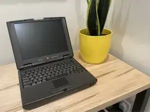
Introduction
-
-
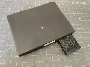
You'll want to check inside the battery compartment. These machines are notorious for their PRAM batteries going critical and leaking electrolytic fluid all over the place. If you see any, grab some gloves.
-
-
-
Open ther monitor so it folds all the way back for the next steps...
-
Remove the plastic hole covers if needed.
-
Remove the two phillips head screws from the top plate.
-
-
-
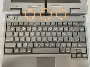
Using a plastic spudger, pop the hinge clips forward by carefully squeezing them forward.
-
With a spudger, push in the two plastic clips in the front behind the F3 and F12 keys.
-
After the hinge covers are loostened, insert your spudger and loosen the rest of the top clips across the back.
-
The top plate should come free.
-
-
-
Use the spudger to push the small plate away from the monitor clips, it should come free easily.
-
-
-
Use your fingers to pull the keyboard cover straight back towards you to release the cips.
-
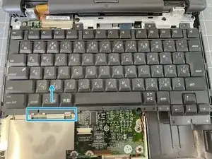
Loosen the trackpad ribbon cable and remove the ribbon.
-
Set the keyboard cover aside.
-
-
-
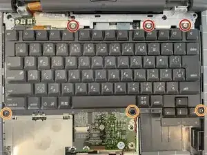
Remove 3 x silver 3mm phillips screws from the top of the keyboard.
-
Remove 3x black 8mm screws from the bottom.
-
Lift the back of the keyboard (the end by the screen) slightly and move it forward to release it from the metal clips at the bottom left. You can then flip the keyboard over and set it on top of the screen.
-
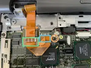
Using a spudger, release the clips from the keyboard connectors and remove the cables from the connectors.
-
-
-
Use a spudger to disconnect the IR assembly ribbon cable from the board.
-
Remove the black 22mm phillips screw from the right side of the assembly.
-
Remove the silver 3mm phillips screw from the left of the assembly.
-
-
-
Remove the black 15mm phillips screw to disconnect the screen ground.
-
Using a spudger, remove the 1st lcd connector.
-
Using a spudger, remove the 2nd LCD connector.
-
-
-
Remove the 2 black 8mm screws from the back.
-
Remove the 2 silver 3mm phillips screws from the front.
-
You can now lift the screen up and out of the chassis.
-
-
-
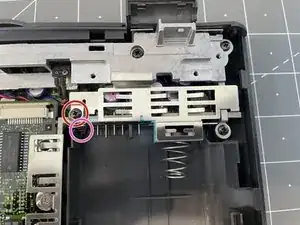
Remove the black 16mm phillips screw.
-
You can now remove this shielding.
-
Make sure to remove and set aside the small spring attached underneath the screw.
-
Remove the two black 8mm phillips screws.
-
You can now lift off the large shielding. Be careful to remove the metal clips on the front of the shielding.
-
-
-
Using a spudger, disconnect the display sleep switch from the board.
-
Remove the 3 black 8mm phillips screws from the outside of the top frame.
-
Remove the 1 black 22mm phillips screw from the top right of the top frame.
-
Remove the 1 black 14mm phillips screw from the middle left of the top frame.
-
Remove the 1 black 4mm phillips screw from the left of the top frame.
-
Lift off the top frame, being careful to unravel the sleep switch cable from around the SCSI port.
-
-
-
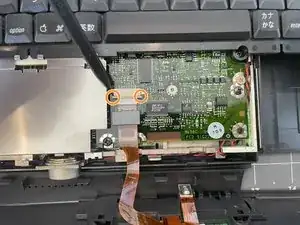
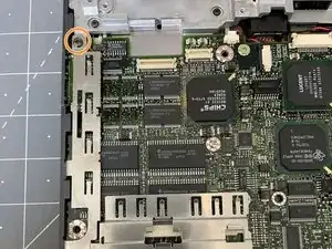
Remove the 2 silver 3.5mm phillips screws from the shielding on the right of the board. You can then remove and set aside the shielding.
-
Remove the 3 remaining silver 3.5mm phillips screws from the system board.
-
Remove the 2 black 16mm phillips screws from the right of the board.
-
Remove the 1 silver 14mm phillips screw from the center of the board.
-
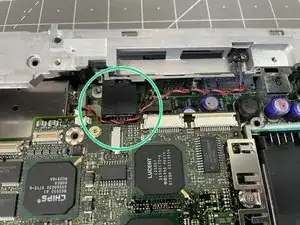
Using a spudger, disconnect the audio cable from the board.
-
Carefully remove the audio port cover by gently twisting upward and lifting out.
-
The main system board is connected to the daugter board below. Using a spudger where indicated to gently coax the board free from the connector below.
-
You can now lift the main board out of the case.
-
-
-
Remove the 2 black 3.5mm phillips screws from the bottom side of the board.
-
Gently, but firmly remove the hard drive from the IDE connector by wiggling back and forth slightly and pulling back toward the side of the board.
-
-
-
Remove the single black 16mm phillips screw holding the plastic assembly to the bottom case.
-
Lift the front of the board (closest to you) to pull the assembly out of the case, making sure clear the ports in the back.
-
-
-
Place the system board on top of the assembly so the PCMCIA slot is to the left of the ports.
-
Carefully flip the assembly over.
-
While supporting the back, gently apply pressure to the highligted area to re-seat the boards. You should feel a positive fit.
-
-
-
Place the boards back into the chassis by tilting to board to the back and inserting them port-first.
-
Replace the black 16mm phillips screw.
-
Replace the small spring.
-


To reassemble your device, make sure you complete the guide.

2 comments
Thank you for posting this guide - I would not be able to successfully disassemble and then reassemble this machine without this help. The first time I disassembled and reassembled my 2400c it would not boot. But then I did it again and now it's booting.
feinberj -
Glad to hear this guide helped! The 2400c is such a great little notebook.
Hrushka -