4

Short Question
Is there a common way to handle very large anomalies (order of magnitude) within an otherwise uniform control region?

Background
I am working on a control algorithm that drives a motor across a generally uniform control region. With no / minimal loading the PID control works great (fast response, little to no overshoot). The issue I'm running into is there will usually be at least one high load location. The position is determined by the user during installation, so there is no reasonable way for me to know when / where to expect it.

When I tune the PID to handle the high load location, it causes large over shoots on the non-loaded areas (which I fully expected). While it is OK to overshoot mid travel, there are no mechanical hard stops on the enclosure. The lack of hardstops means that any significant overshoot can / does cause the control arm to be disconnected from the motor (yielding a dead unit).

Things I'm Prototyping

  • Nested PIDs (very agressive when far away from target, conservative when close by)
  • Fixed gain when far away, PID when close
  • Conservative PID (works with no load) + an external control that looks for the PID to stall and apply additional energy until either: the target is achieved or rapid rate of change is detected (ie leaving the high load area)

Hardware Limitations

  • Full travel defined
  • Hardstops cannot be added (at this point in time)

Update
My answer does not indicate that this is best solution. It's just my current solution that I thought I would share.
Jonas
  • 121,568
  • 97
  • 310
  • 388
Adam Lewis
  • 7,017
  • 7
  • 44
  • 62

1 Answers1

0

Initial Solution

stalled_pwm_output = PWM / | ΔE |

PWM = Max PWM value
ΔE = last_error - new_error

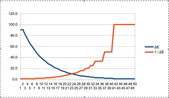
The initial relationship successfully ramps up the PWM output based on the lack of change in the motor. See the graph below for the sample output.

This approach makes since for the situation where the non-aggressive PID stalled. However, it has the unfortunate (and obvious) issue that when the non-aggressive PID is capable of achieving the setpoint and attempts to slow, the stalled_pwm_output ramps up. This ramp up causes a large overshoot when traveling to a non-loaded position.

1/ΔE vs ΔE

Current Solution

Theory

stalled_pwm_output = (kE * PID_PWM) / | ΔE |

kE = Scaling Constant
PID_PWM = Current PWM request from the non-agressive PID
ΔE = last_error - new_error

My current relationship still uses the 1/ΔE concept, but uses the non-aggressive PID PWM output to determine the stall_pwm_output. This allows the PID to throttle back the stall_pwm_output when it starts getting close to the target setpoint, yet allows 100% PWM output when stalled. The scaling constant kE is needed to ensure the PWM gets into the saturation point (above 10,000 in graphs below).

Pseudo Code

Note that the result from the cal_stall_pwm is added to the PID PWM output in my current control logic.

int calc_stall_pwm(int pid_pwm, int new_error)
{
    int ret = 0;
    int dE = 0;
    static int last_error = 0;
    const int kE = 1;

    // Allow the stall_control until the setpoint is achived
    if( FALSE == motor_has_reached_target())
    {
        // Determine the error delta
        dE = abs(last_error - new_error);
        last_error = new_error;

        // Protect from divide by zeros
        dE = (dE == 0) ? 1 : dE;

        // Determine the stall_pwm_output
        ret = (kE * pid_pwm) / dE;
    }

    return ret;
}

Output Data

Stalled PWM Output Stalled PWM Output

Note that in the stalled PWM output graph the sudden PWM drop at ~3400 is a built in safety feature activated because the motor was unable to reach position within a given time.

Non-Loaded PWM Output No-Load PWM Output

Adam Lewis
  • 7,017
  • 7
  • 44
  • 62