11

I am trying to detect the vehicle from the video , I 'll do it in real time application but for the time being and for good understanding i am doing it on video , code is below:

void surf_detection(Mat img_1,Mat img_2); /** @function main */

int main( int argc, char** argv )
{

 int i;
 int key;

 CvCapture* capture = cvCaptureFromAVI("try2.avi");// Read the video file

 if (!capture){

     std::cout <<" Error in capture video file";
     return -1;
 }

 Mat img_template = imread("images.jpg"); // read template image

int numFrames = (int) cvGetCaptureProperty(capture,  CV_CAP_PROP_FRAME_COUNT);


IplImage* img = 0; 

for(i=0;i<numFrames;i++){
  cvGrabFrame(capture);          // capture a frame
  img=cvRetrieveFrame(capture);  // retrieve the captured frame


  surf_detection (img_template,img);

  cvShowImage("mainWin", img); 
  key=cvWaitKey(20);           

}

 return 0;
 }

void surf_detection(Mat img_1,Mat img_2)
{ 

if( !img_1.data || !img_2.data )
{ 
    std::cout<< " --(!) Error reading images " << std::endl; 

}


//-- Step 1: Detect the keypoints using SURF Detector
int minHessian = 400;
SurfFeatureDetector detector( minHessian );
std::vector<KeyPoint> keypoints_1, keypoints_2;

std::vector< DMatch > good_matches;

do{ 

detector.detect( img_1, keypoints_1 );
detector.detect( img_2, keypoints_2 );

//-- Draw keypoints

Mat img_keypoints_1; Mat img_keypoints_2;
drawKeypoints( img_1, keypoints_1, img_keypoints_1, Scalar::all(-1), DrawMatchesFlags::DEFAULT );
drawKeypoints( img_2, keypoints_2, img_keypoints_2, Scalar::all(-1), DrawMatchesFlags::DEFAULT );

//-- Step 2: Calculate descriptors (feature vectors)
SurfDescriptorExtractor extractor;
Mat descriptors_1, descriptors_2;
extractor.compute( img_1, keypoints_1, descriptors_1 );
extractor.compute( img_2, keypoints_2, descriptors_2 );


//-- Step 3: Matching descriptor vectors using FLANN matcher
FlannBasedMatcher matcher;
std::vector< DMatch > matches;
matcher.match( descriptors_1, descriptors_2, matches );
double max_dist = 0; 
double min_dist = 100;

//-- Quick calculation of max and min distances between keypoints
for( int i = 0; i < descriptors_1.rows; i++ )
{ 
    double dist = matches[i].distance;
if( dist < min_dist )
    min_dist = dist;
if( dist > max_dist ) 
    max_dist = dist;
}


//-- Draw only "good" matches (i.e. whose distance is less than 2*min_dist )


for( int i = 0; i < descriptors_1.rows; i++ )
{ 
    if( matches[i].distance < 2*min_dist )
        { 
                good_matches.push_back( matches[i]);
        }
}

}while(good_matches.size()<100);

//-- Draw only "good" matches
Mat img_matches;
drawMatches( img_1, keypoints_1, img_2, keypoints_2,good_matches, img_matches, Scalar::all(-1), Scalar::all(-1),
vector<char>(), DrawMatchesFlags::NOT_DRAW_SINGLE_POINTS );

//-- Localize the object
std::vector<Point2f> obj;
std::vector<Point2f> scene;
for( int i = 0; i < good_matches.size(); i++ )
{
//-- Get the keypoints from the good matches
obj.push_back( keypoints_1[ good_matches[i].queryIdx ].pt );
scene.push_back( keypoints_2[ good_matches[i].trainIdx ].pt );
}


Mat H = findHomography( obj, scene, CV_RANSAC );


//-- Get the corners from the image_1 ( the object to be "detected" )
std::vector<Point2f> obj_corners(4);
obj_corners[0] = Point2f(0,0); 
obj_corners[1] = Point2f( img_1.cols, 0 );
obj_corners[2] = Point2f( img_1.cols, img_1.rows ); 
obj_corners[3] = Point2f( 0, img_1.rows );
std::vector<Point2f> scene_corners(4);

perspectiveTransform( obj_corners, scene_corners, H);

//-- Draw lines between the corners (the mapped object in the scene - image_2 )
line( img_matches, scene_corners[0] , scene_corners[1] , Scalar(0, 255, 0), 4 );
line( img_matches, scene_corners[1], scene_corners[2], Scalar( 0, 255, 0), 4 );
line( img_matches, scene_corners[2] , scene_corners[3], Scalar( 0, 255, 0), 4 );
line( img_matches, scene_corners[3] , scene_corners[0], Scalar( 0, 255, 0), 4 );
imshow( "Good Matches & Object detection", img_matches );

}

I am getting the following output

enter image description here

and std::cout << scene_corners[i] (Result)

std::cout << scene_corners[i] (Result)

Value of H:

enter image description here

But my question is why its not drawing rectangle on the object which is detected like:

Rectangle is visible on detected object

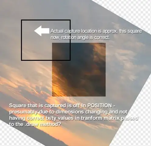
I am doing this on simple video and image , but when i did it on still camera so it may difficult without that rectangle

  • as mentioned below in answers this question is a duplicate of http://stackoverflow.com/questions/11049081/drawing-rectangle-around-detected-object-using-surf?rq=1 – masad Jul 16 '13 at 09:14
  • @masad I think that answer is not working for me , you can check it out –  Jul 16 '13 at 17:27
  • Check homography matrix H and post here result. With new opencv interface it can be done as cout< – mrgloom Jul 18 '13 at 12:13
  • @mrgloom I update the result of Mat H –  Jul 22 '13 at 13:32
  • You can't apply sift features for "different" objects like on your picture http://i.stack.imgur.com/RfrYH.png , but you can try constellation model based on SIFT features instead (machine learning will be involved) – mrgloom Jul 23 '13 at 05:48

4 Answers4

8

First, in the image you show, no rectangle is drawn at all. Can you draw a rectangle, say, in the middle of your image?

Then, looking at the following code:

int x1 , x2 , y1 , y2 ;
x1 = scene_corners[0].x + Point2f( img_1.cols, 0).x ; 
y1 = scene_corners[0].y + Point2f( img_1.cols, 0).y ; 
x2 = scene_corners[0].x + Point2f( img_1.cols, 0).x + in_box.width ; 
y2 = scene_corners[0].y + Point2f( img_1.cols, 0).y + in_box.height ;

I don't see why you add in_box.width and in_box.height to each corner (where are they defined?). You should use scene_corners[2] instead. But the commented lines should print a rectangle somewhere.

Since you asked for more details, let's see what happens in your code.

First, how do you get to perspectiveTransform()?

  1. You detect feature points using detector.detect. It gives you points of interest in both images.
  2. You describe those features using extractor.compute. It gives you a way to compare points of interest. Comparing the descriptors of two features answers the question: How similar are those points?*
  3. You actually compare each feature on the first image to all of the features in the second image (sort of), and keep the best match for each feature. At this point, you know the pairs of features that look the most similar.
  4. You only keep the good_matches. Because it can happen that for one feature, the most similar one in the other image is actually completely different (it is still the most similar since you had no better choice). This is a first filter to remove wrong matches.
  5. You find a homography transform corresponding to the matches you have found. It means that you try to find how a point in the first image should be projected in the second image. The homography matrix you get then allows you to project any point of the first image on its correspondence in the second image.

Second, what do you do with this?

Now it becomes interesting. You have a homography matrix that allows you to project any point of the first image onto its correspondence in the second image. So you can decide to draw a rectangle around your object (that is obj_corners), and to project it on the second image (perspectiveTransform( obj_corners, scene_corners, H);). The result is in scene_corners.

Now you want to draw a rectangle using scene_corners. But there is one more point: drawMatches() apparently puts both of your images next to each other in img_matches. But the projection (homography matrix) was computed on the images separately! Which means that each scene_corner must be translated accordingly. Since the scene image was drawn on the right of the object image, then you must add the width of the object image to each scene_corner in order to translate them to the right.

That's why you add 0 to y1 and y2 since you don't have to translate them vertically. But for x1 and x2, you have to add img_1.cols.

//-- Draw lines between the corners (the mapped object in the scene - image_2 )
line( img_matches, scene_corners[0] + Point2f( img_1.cols, 0), scene_corners[1] + Point2f( img_1.cols, 0), Scalar(0, 255, 0), 4 );
line( img_matches, scene_corners[1] + Point2f( img_1.cols, 0), scene_corners[2] + Point2f( img_1.cols, 0), Scalar( 0, 255, 0), 4 );
line( img_matches, scene_corners[2] + Point2f( img_1.cols, 0), scene_corners[3] + Point2f( img_1.cols, 0), Scalar( 0, 255, 0), 4 );
line( img_matches, scene_corners[3] + Point2f( img_1.cols, 0), scene_corners[0] + Point2f( img_1.cols, 0), Scalar( 0, 255, 0), 4 );

So I would suggest that you uncomment those lines and see if a rectangle is drawn. If not, try to hard code values (e.g. Point2f(0, 0) and Point2f(100, 100)) until your rectangle is drawn successfully. Maybe your problem comes from the use of cvPoint and Point2f together. Also try to use Scalar(0, 255, 0, 255)...

Hope it helps.

*It must be understood that two points might look exactly the same but not correspond to the same point in reality. Think about a really repetitive pattern such as the corners of windows on a building. All of the windows look the same, so the corners of two different windows might look really similar even though this is clearly a wrong match.

JonasVautherin
  • 7,297
  • 6
  • 49
  • 95
  • Well thanks for such a nice explanation , for which i am waiting for , +1, and those lines which you ask for uncomment ya uncommneted in my implementation , and i want to draw a square around detected object , like which i show in the example image above. –  Jul 17 '13 at 11:22
  • Did you success in drawing a hard-coded rectangle as I suggested? Your image shows absolutely no rectangle, which let think that the drawing itself is not working. Try to draw a rectangle between point (0, 0) and (100, 100) and let me know if it works. – JonasVautherin Jul 17 '13 at 12:41
  • Yes , when i use point (0,0) or someother values it draw a dot some where on the image , i am detecting the vehicle from video , i want it when it detect the vehicle i should mark it in a square or reactangle , and video keep running , i update my code –  Jul 17 '13 at 14:07
  • Can you tell me what the values of `scene_corners` are after `perspectiveTransform()`? – JonasVautherin Jul 17 '13 at 14:43
  • the common values of frames ?? –  Jul 18 '13 at 10:37
  • You told me that you were able to draw a rectangle by hard coding the values (it drew a dot since you used the same value everywhere). It means that the drawing function works. Therefore, you need to verify the values you have in `scene_corner[...]`. Just try to print them for each frame and give me the value of one of them. I just want to see if it is consistent or not. – JonasVautherin Jul 18 '13 at 10:52
  • `scene_corners[0] + Point2f( 0, 50), scene_corners[1] + Point2f( 0, 50) scene_corners[1] + Point2f( 0, 50), scene_corners[2] + Point2f( 0, 50), scene_corners[2] + Point2f( 0, 50), scene_corners[3] + Point2f( 0, 50), scene_corners[3] + Point2f( 0, 50), scene_corners[0] + Point2f( 0, 50),` –  Jul 18 '13 at 11:15
  • I want to know the values in `scene_corner[0]`, `scene_corner[1]`, etc. If those four lines draw a dot, it means that all of the points are the same. And they should not. Do you understand what those four lines are supposed to do? – JonasVautherin Jul 18 '13 at 12:39
  • 1
    Whats he want to write in output video ? not getting that point – Rocket Jul 20 '13 at 10:16
  • What was the solution eventually? – JonasVautherin Jul 21 '13 at 15:16
  • @JonesV If i didn't select the answer so answer will selected automatically so i accept your answer because it help although it not solve my problem , still , if rectangle is not drawn or square , i just want that if i detect the vehicle than video should keep moving not stop there after detection –  Jul 22 '13 at 10:59
  • @Wish_2_fly I think you should remove the code of writing video if you want to apply it on real time, so its easy for you to understand it better , and make it simple if u can , so its easy to understand and rewrite code as answer – Rocket Jul 22 '13 at 11:04
  • @Angel No body help me to rewrite it in new format(interface) and guide me to code it better , i am new to opencv ,and there are not enough programmer of opencv on this forum as compared to others –  Jul 22 '13 at 11:10
  • After your call of `perspectiveTransform`, add: `for (int i = 0; i < 4; i++) { std::cout << scene_corner[i] << std::endl; }` and tell me what it prints. – JonasVautherin Jul 22 '13 at 11:52
  • The values seem quite nice. Can you add a picture with the rectangle drawn (actually you said you have a "dot")? And remove the `Point2f(0, 50)` that you added for each `line`... – JonasVautherin Jul 22 '13 at 12:57
  • okay let me add it , but my video car is not as same as i give it in sample , in sample i have a front view and in video i am getting video from up side –  Jul 22 '13 at 13:07
  • @JonesV I update every thing include my code and try to make it simple , i update output pictures , i hope now the green solid line clearly visible to you –  Jul 22 '13 at 13:32
  • Okay, the matching simply doesn't work for these images. As a first test, use twice the same image and see if your code works... – JonasVautherin Jul 22 '13 at 14:24
  • let us [continue this discussion in chat](http://chat.stackoverflow.com/rooms/33916/discussion-between-jonesv-and-wish-2-fly) – JonasVautherin Jul 22 '13 at 14:32
2

You did the following steps:

  1. Match key points in 2 images.
  2. Assuming the match was correct, calculate homography (projection matrix).
  3. Use the homography to project the corners of original image to draw a quadrilateral shape (which you refer to as rectangle under) perspective transformation.

The problem you are having is that when step 1 fails you get a wrong homography in step 2 (wrong matrix) and when you project the corners in step 3, they can fall out of the image and you don't see the lines.

What you actually want is a way to know whether the homography you calculated is of a correct form. To do this please see the answer here: How to check if obtained homography matrix is good? Use it to test if your homography is correct. If not, you know that the match resulted in a failure. If it is correct, you can draw a rectangle and you will see it but it might be not so accurate if the match between key points was not accurate.

Finally, I think that your algorithmic approach is wrong. Recognizing/detecting a vehicle from top view by matching it to image of vehicle from frontal view is a dead end. You should not use key points matching at all. Just mark manually all the vehicles on the images and send it to SVM. If this is too much work use Mechanical Turk platform to label the vehicles automatically. In conclusion - key points match is an approach that just does not suits your needs because it has a strong assumption that the appearance of the car in both images is similar. In your case those images are too different (due to the 3D structure of the car and different viewing angles)

Community
  • 1
  • 1
DanielHsH
  • 4,287
  • 3
  • 30
  • 36
  • 1
    I am not sure that surf are the right features. Why do you think that SURF features will capture the difference between cars? SURF catches very small local variations (like cellphone on the dashboard, or the person in the drivers seat) while cars marks are different in big scale (shape/size). I would use large features features like ratio of car width to length, color, shape of the contour of the car. Image patches from the front and the rear of the car, patch in the front of the car which captures the symbol, etc... If you use local features, calculate histograms and use them as descriptors – DanielHsH Jul 23 '13 at 19:04
1

What you are actually doing is to find reference points within images (key points) and comparing them to each other to find them re-occurring in another images (based on the SURF feature vector). This is an important step in object detection and recognition, but is not to be mistaken with image segmentation (http://en.wikipedia.org/wiki/Image_segmentation) or object localization, where you find the exact outlines (or set of pixels or superpixels) of the desired object.

Getting a bounding rectangle of an object, especially one put into perspective as in your example, is not a trivial task. You might start with a bounding box of key points that have been found. However, this will only cover part of the object. Especially the bounding box in perspective in your example might be hard to find without 3D registration of the image, i.e. knowing the 3rd dimension value (z-value, depth) of each pixel in the image.

Mathias
  • 324
  • 1
  • 5
  • 1
    I saw Surf documentation and there i found that rectangle as output result, no segmentation was mention there –  Jul 10 '13 at 18:36
1

Same as this? Drawing rectangle around detected object using SURF

As far as I can tell, the only reason the outline isn't drawn is because the section of code that does that is commented out, so uncomment it. This portion of code outlined a test image for me:

/*   
//-- Draw lines between the corners (the mapped object in the scene - image_2 )
line( img_matches, scene_corners[0] + Point2f( img_1.cols, 0), scene_corners[1] + Point2f( img_1.cols, 0), Scalar(0, 255, 0), 4 );
line( img_matches, scene_corners[1] + Point2f( img_1.cols, 0), scene_corners[2] + Point2f( img_1.cols, 0), Scalar( 0, 255, 0), 4 );
line( img_matches, scene_corners[2] + Point2f( img_1.cols, 0), scene_corners[3] + Point2f( img_1.cols, 0), Scalar( 0, 255, 0), 4 );
line( img_matches, scene_corners[3] + Point2f( img_1.cols, 0), scene_corners[0] + Point2f( img_1.cols, 0), Scalar( 0, 255, 0), 4 );   */

You probably don't want to draw a rectangle around the matched template in the video image because it may be warped. Connect the warped scene_corners with lines, instead. I would remove all that x1, x2, y1, y2 and cvRect square stuff.

Note that scene_corners does not give you a rectangle because the object may be rotated in the video differently than it is in the template image. The cell phone image posted above is a great example, - the green outline around the phone's screen is a a quadrilateral. If you want to work with a rectangular ROI the contains the entire object, you might consider finding the bounding rectangle that contains the entire object in the video. Here's how I'd do that:

// draw the *rectangle* that contains the entire detected object (a quadrilateral)
// i.e. bounding box in the scene (not the corners)

// upper left corner of bounding box
cv::Point2f low_bound = cv::Point2f( min(scene_corners[0].x, scene_corners[3].x) , min(scene_corners[0].y, scene_corners[1].y) );

// lower right corner of bounding box
cv::Point2f high_bound = cv::Point2f( max(scene_corners[2].x, scene_corners[1].x) , max(scene_corners[2].y, scene_corners[3].y) );

// bounding box offset introduced by displaying the images side-by-side
// *only for side-by-side display*
cv::Point2f matches_offset = cv::Point2f( img_1.cols, 0);

// draw the bounding rectangle in the side-by-side display
cv::rectangle( img_matches , low_bound +  matches_offset , high_bound + matches_offset , cv::Scalar::all(255) , 2 );

/* 
if you want the rectangle around the object in the original video images, don't add the
offset and use the following line instead:

cv::rectangle( img_matches , low_bound , high_bound , cv::Scalar::all(255) , 2 );
*/

// Here is the actual rectangle, you can use as the ROI in you video images:
cv::Rect video_rect = cv::Rect( low_bound , high_bound );

The last line in the code block above might have the rectangle you were trying to get in your originally posted code. It should be the rectangle in your video image, img. You can use it to work with the subset of you image that contains the object (an ROI).

As Anum mentioned, you're also mixing the old and new OpenCV style. You could clean things up by consistently using Point2f rather than cvPoint, among other things.

Community
  • 1
  • 1
  • Grigole what is low_bound , high_bound , matches_offset ? –  Jul 17 '13 at 11:16
  • See the updates above. `scene_corners` do not necessarily form an upright rectangle in the video - the object may have turned or rotated. `low_bound` and `high_bound` give the upper left and lower right corners of a bounding rectangle that contains your object. `matches_offset` is used to display the rectangle when the images are side-by-side after calling `findMatches`. You don't add that if you want the rectangle in your raw video image. – Mike Grigola Jul 18 '13 at 00:31