Interesting problem! The "cute" part is the effect on the intrinsic parameters of the refraction at the water-glass interface, namely to increase the focal length (or, conversely, to reduce the field of view) compared to the same lens in air. In theory, you could calibrate in air and then correct for the difference in refraction index, but calibrating directly in water is likely to give you more accurate results.
Do know your accuracy requirements? And have you verified that your lens/sensor combination is adequate to meet them (with an adequate margin)? To answer the question you need to estimate (either by calculation from the lens and sensor specifications, or experimentally using a resolution chart) whether you can resolve in an image the minimal distances required by your application.
From the wording of your question I think that you are interested only in measurements on a single plane. So you only need to (a) remove the nonlinear (barrel or pincushion) lens distortion and (b) estimate the homography between the plane of interest and the image. Once you have the latter, you can directly convert from undistorted image coordinates to world ones by matrix multiplication. Additionally if (as I imagine) the plane of interest is roughly parallel to the image plane, you should not have any problem keeping the entire field-of-view in focus.
Of course, for all of this to work as expected, you should make sure that the tank bottom is really flat, within the measurement tolerances of your application. Otherwise you are really dealing with a 3D problem, and need to modify your procedures accordingly.
The actual procedure depends a lot on the size of the tank, which you don't indicate clearly. If it's small enough that it is practical to manufacture a chessboard-like movable calibration target, by all means go for it. You may want to take a look at this other answer for suggestions. In the following I'll discuss the more interesting case in which your tank is large, e.g. the size of a swimming pool.
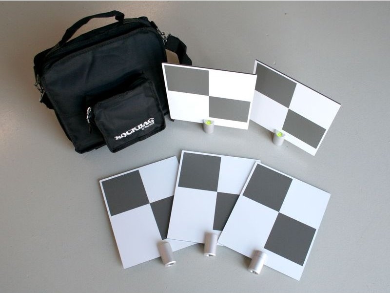
I'd proceed by sticking calibration markers in a regular grid at the pool bottom. I'd probably choose checker-like markers like these, maybe printing them myself with a good laser printer on plastic with an adhesive backing (assuming you can leave them in place forever). You should plan on having quite a few of them, say, an 8x8 or 10x10 grid, covering as much as possible of the field of view of the camera in its operating position and pose. To help with lining up the grid nicely you might use a laser line projector of suitable fan angle, or a laser pointer attached to a rotating support. Note carefully that it is not necessary that they be affixed in a precise X-Y grid (which may be complicated, depending on the size of your pool), only that their positions with respect any arbitrarily chosen (but fixed) three of them be known. In other words, you can attach them to the bottom approximately in a grid, then measure the distances of three extreme corners from each other as accurately as you can, thus building a base triangle, then measure the distances of all the other corners from the vertices of the triangle, and finally reconstruct their true positions with a bit of trigonometry. It's basically a surveying problem and, depending on your accuracy requirements and budget, you may want to enroll a local friendly professional surveyor (and their tools) to get it done as precisely as necessary.
Once you have your grid, you can fill the pool, get your camera, focus and f-stop the lens as needed for the application. From now on you may not touch the focus and f-stop ever again, under penalty of miscalibrating - exposure can only be controlled by the exposure time, so make sure to have enough light. Disable any and all auto-focus and auto-iris functions, if any. If the camera has a non-rigid lens mount (e.g. a DLSR), you'll need some kind of mechanical rig to ensure that the lens-body pair stay rigid. F-stop as close as you can, given the available lighting and sensor, so to have a fair bit of depth of field available. Then take several photos (~ 10) of the grid, moving and rotating the camera, and going a bit closer and farther away than your expected operating distance from the plane. You'll want to "see" in some images some significant perspective foreshortening of the grid - this is needed to accurately calibrate the focal length. Avoid JPG and any other lossy compression format when storing the images - use lossless PNG or TIFF.
Once you have the images, you can manually mark and identify the checker markers in the images. For a once-off project like this I would not bother with automatic identification, just do it manually (e.g. in Matlab, or even in Photoshop or Gimp). To help identify the markers, you could, e.g. print a number next to them. Once you have the manual marks, you can refine them automatically to subpixel accuracy, e.g. using cv::findCornerSubpix.
You're almost done. Feed the "reference" measured position of the real corners, and the observed ones in all images, to your favorite camera calibration routine, e.g. cv::calibrateCamera. You use the nominal focal length of the camera (converted to pixels) for an initial estimate, along with null distortion. If all goes well, you will obtain the camera intrinsic parameters, which you will keep, and the camera poses at all images, which you'll throw away.
Now you can mount the camera in your final setup, as needed by your application, and take one further image of the grid. Mark and refine the corner positions as before. Undistort their image positions using the distortion parameters returned by the calibration. Finally compute the homography between the reference positions of the real markers (in meters) and their undistorted positions, and you're done.
HTH