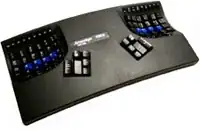
I have been working a self project in image processing and robotics where instead robot as usual detecting colors and picking out the object, it tries to detect the holes(resembling different polygons) on the board. For a better understanding of the setup here is an image:

As you can see I have to detect these holes, find out their shapes and then use the robot to fit the object into the holes. I am using a kinect depth camera to get the depth image. The pic is shown below:
I was lost in thought of how to detect the holes with the camera, initially using masking to remove the background portion and some of the foreground portion based on the depth measurement,but this did not work out as, at different orientations of the camera the holes would merge with the board... something like inranging (it fully becomes white). Then I came across adaptiveThreshold function
adaptiveThreshold(depth1,depth3,255,ADAPTIVE_THRESH_GAUSSIAN_C,THRESH_BINARY,7,-1.0);
With noise removal using erode, dilate, and gaussian blur; which detected the holes in a better manner as shown in the picture below. Then I used the cvCanny edge detector to get the edges but so far it has not been good as shown in the picture below.After this I tried out various feature detectors from SIFT, SURF, ORB, GoodFeaturesToTrack and found out that ORB gave the best times and the features detected. After this I tried to get the relative camera pose of a query image by finding its keypoints and matching those keypoints for good matches to be given to the findHomography function. The results are as shown below as in the diagram:
In the end i want to get the relative camera pose between the two images and move the robot to that position using the rotational and translational vectors got from the solvePnP function.
So is there any other method by which I could improve the quality of the holes detected for the keypoints detection and matching?
I had also tried contour detection and approxPolyDP but the approximated shapes are not really good:
I have tried tweaking the input parameters for the threshold and canny functions but this is the best I can get
Also ,is my approach to get the camera pose correct?
UPDATE : No matter what I tried I could not get good repeatable features to map. Then I read online that a depth image is cheap in resolution and its only used for stuff like masking and getting the distances. So , it hit me that the features are not proper because of the low resolution image with its messy edges. So I thought of detecting features on a RGB image and using the depth image to get only the distances of those features. The quality of features I got were literally off the charts.It even detected the screws on the board!! Here are the keypoints detected using GoodFeaturesToTrack keypoint detection. .
I met an another hurdle while getting the distancewith the distances of the points not coming out properly. I searched for possible causes and it occured to me after quite a while that there was a offset in the RGB and depth images because of the offset between the cameras.You can see this from the first two images. I then searched the net on how to compensate this offset but could not find a working solution.
.
I met an another hurdle while getting the distancewith the distances of the points not coming out properly. I searched for possible causes and it occured to me after quite a while that there was a offset in the RGB and depth images because of the offset between the cameras.You can see this from the first two images. I then searched the net on how to compensate this offset but could not find a working solution.
If anyone one of you could help me in compensate the offset,it would be great!
UPDATE: I could not make good use of the goodFeaturesToTrack function. The function gives the corners in Point2f type .If you want to compute the descriptors we need the keypoints and converting Point2f to Keypoint with the code snippet below leads to the loss of scale and rotational invariance.
for( size_t i = 0; i < corners1.size(); i++ )
{
keypoints_1.push_back(KeyPoint(corners1[i], 1.f));
}
The hideous result from the feature matching is shown below  .
.
I have to start on different feature matchings now.I'll post further updates. It would be really helpful if anyone could help in removing the offset problem.