3

I'm trying to implement the method of improving fingerprint images by Anil Jain. As a starter, I encountered some difficulties while extracting the orientation image, and am strictly following those steps described in Section 2.4 of that paper.

So, this is the input image:

enter image description here

And this is after normalization using exactly the same method as in that paper:

enter image description here

I'm expecting to see something like this (an example from the internet):

enter image description here

However, this is what I got for displaying obtained orientation matrix:

enter image description here

Obviously this is wrong, and it also gives non-zero values for those zero points in the original input image.

This is the code I wrote:

cv::Mat orientation(cv::Mat inputImage)
{
    cv::Mat orientationMat = cv::Mat::zeros(inputImage.size(), CV_8UC1);

    // compute gradients at each pixel
    cv::Mat grad_x, grad_y;
    cv::Sobel(inputImage, grad_x, CV_16SC1, 1, 0, 3, 1, 0, cv::BORDER_DEFAULT);
    cv::Sobel(inputImage, grad_y, CV_16SC1, 0, 1, 3, 1, 0, cv::BORDER_DEFAULT);

    cv::Mat Vx, Vy, theta, lowPassX, lowPassY;
    cv::Mat lowPassX2, lowPassY2;

    Vx = cv::Mat::zeros(inputImage.size(), inputImage.type());
    Vx.copyTo(Vy);
    Vx.copyTo(theta);
    Vx.copyTo(lowPassX);
    Vx.copyTo(lowPassY);
    Vx.copyTo(lowPassX2);
    Vx.copyTo(lowPassY2);

    // estimate the local orientation of each block
    int blockSize = 16;

    for(int i = blockSize/2; i < inputImage.rows - blockSize/2; i+=blockSize)
    {    
        for(int j = blockSize / 2; j < inputImage.cols - blockSize/2; j+= blockSize)
        {
            float sum1 = 0.0;
            float sum2 = 0.0;

            for ( int u = i - blockSize/2; u < i + blockSize/2; u++)
            {
                for( int v = j - blockSize/2; v < j+blockSize/2; v++)
                {
                    sum1 += grad_x.at<float>(u,v) * grad_y.at<float>(u,v);
                    sum2 += (grad_x.at<float>(u,v)*grad_x.at<float>(u,v)) * (grad_y.at<float>(u,v)*grad_y.at<float>(u,v));
                }
            }

            Vx.at<float>(i,j) = sum1;
            Vy.at<float>(i,j) = sum2;

            double calc = 0.0;

            if(sum1 != 0 && sum2 != 0)
            {
                calc = 0.5 * atan(Vy.at<float>(i,j) / Vx.at<float>(i,j));
            }

            theta.at<float>(i,j) = calc;

            // Perform low-pass filtering
            float angle = 2 * calc;
            lowPassX.at<float>(i,j) = cos(angle * pi / 180);
            lowPassY.at<float>(i,j) = sin(angle * pi / 180);

            float sum3 = 0.0;
            float sum4 = 0.0;

            for(int u = -lowPassSize / 2; u < lowPassSize / 2; u++)
            {
               for(int v = -lowPassSize / 2; v < lowPassSize / 2; v++)
               {
                  sum3 += inputImage.at<float>(u,v) * lowPassX.at<float>(i - u*lowPassSize, j - v * lowPassSize);
                  sum4 += inputImage.at<float>(u, v) * lowPassY.at<float>(i - u*lowPassSize, j - v * lowPassSize);
               }
            }
        lowPassX2.at<float>(i,j) = sum3;
        lowPassY2.at<float>(i,j) = sum4;

        float calc2 = 0.0;

        if(sum3 != 0 && sum4 != 0)
        {
           calc2 = 0.5 * atan(lowPassY2.at<float>(i, j) / lowPassX2.at<float>(i, j)) * 180 / pi;
        }
        orientationMat.at<float>(i,j) = calc2;

        }

    }
return orientationMat;

}

I've already searched a lot on the web, but almost all of them are in Matlab. And there exist very few ones using OpenCV, but they didn't help me either. I sincerely hope someone could go through my code and point out any error to help. Thank you in advance.

Update

Here are the steps that I followed according to the paper:

  1. Obtain normalized image G.
  2. Divide G into blocks of size wxw (16x16).
  3. Compute the x and y gradients at each pixel (i,j).
  4. Estimate the local orientation of each block centered at pixel (i,j) using equations: enter image description here

  5. Perform low-pass filtering to remove noise. For that, convert the orientation image into a continuous vector field defined as:

enter image description here

enter image description here

where W is a two-dimensional low-pass filter, and w(phi) x w(phi) is its size, which equals to 5.

  1. Finally, compute the local ridge orientation at (i,j) using:
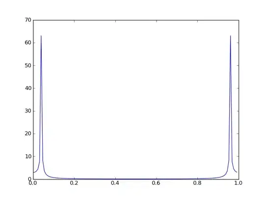
enter image description here

Update2

This is the output of orientationMat after changing the mat type to CV_16SC1 in Sobel operation as Micka suggested:

enter image description here

E_learner
  • 3,512
  • 14
  • 57
  • 88
  • 2
    the orientation matrix gives you the orientation angle at a given point. Now you should not draw the orientation matrix but draw lines with that angle orientation on an image for each given point... – Micka Jan 28 '15 at 13:49
  • Thank you. But why then it gives me non-zero angle values for those zero pixels (top left corner points for instance) ? So there must be something wrong in my code but I still couldn't find it. – E_learner Jan 29 '15 at 07:02
  • 1
    didnt look at your algorithm tbh... can you add some pseudo code and corresponding code comments that explain what you want to do? – Micka Jan 29 '15 at 07:17
  • 1
    Is orientationMat created somewhere? As far as I see it should be an empty Mat and you should get runtime errors in your function when setting element values... – Micka Jan 29 '15 at 07:21
  • I created orientationMat as a zero mat during initialization, and I updated my question to contain description of steps I took. Thank you. – E_learner Jan 29 '15 at 08:02
  • 1
    in your provided code you declare but dont initialize orientationMat?!? So orientationMat.at(i,j) = calc2; should give error... please provide full code of that function! – Micka Jan 29 '15 at 08:45
  • 2
    One problem in your code: your sobel result is 8UC1 which cant handle negative results and should be changed to 16SC1 – Micka Jan 29 '15 at 08:48
  • At the starting point of orientation function, I declared: cv::Mat orientationMat = cv::Mat::zeros(inputImage.size(), CV_8UC1); – E_learner Jan 29 '15 at 08:57
  • 1
    in the code you posted it is declared: `cv::Mat Vx, Vy, theta, lowPassX, lowPassY, orientationMat;` and no initialization... next occurance of orientationMat is `orientationMat.at(i,j) = calc2;`. Please update the provided code if it differs – Micka Jan 29 '15 at 09:00
  • 1
    like @Micka said, please use CV_16S (or CV_32F even) for the Sobel, as well as for your orientation Mat . also make sure, that your at matches the actual image type (you can't *choose* that at will) – berak Jan 29 '15 at 09:01
  • Thank you again for your answer. I updated my code. Could you take a look at it? – E_learner Jan 29 '15 at 09:09
  • 1
    when I launch your code with the provided image (converted to grayscale) and adding `int lowPassSize = 5; float pi = CV_PI;` it crashes somewhere... I think you have to initialize lowPass and all the other Mats too? Can you provide a launchable function code? – Micka Jan 29 '15 at 09:12
  • 1
    @Berak is right, since you access gradients (an all the other matrices) with `.at` later, you have to choose type `CV_32FC1` – Micka Jan 29 '15 at 09:15
  • 1
    there is another problem in your code: how did you choose `lowPassSize`? `for(int u = -lowPassSize / 2; u < lowPassSize / 2; u++)` will probably start with a negative value which will crash `sum3 += inputImage.at(u,v) * ...` – Micka Jan 29 '15 at 09:22
  • Very good point. I didn't notice that part in my code, and for some magic reason, it didn't crash either. I looked again into the algorithm description, and it says W is a two-dimensional low-pass filter. I just used somekind of Gaussian operation in my case. I searched again for creating a two-dimensional low pass filter with opencv, but most of them discuss Fourier transform. Do you have any idea on this point? Thank you again. – E_learner Jan 29 '15 at 09:46
  • 1
    I dont understand that lowpassfilter part, before lpf you have a matrix with 1 value per 16x16-block and the rest of the block is 0. If you lpf that you'll get a matrix with 0 everywhere?!? – Micka Jan 29 '15 at 10:27
  • 1
    you can use `cv::GaussianBlur` to apply a gauss-filter – Micka Jan 29 '15 at 10:28
  • 1
    you've one formular wrong... paper says `Vy = gx^2 - gy^2` you used `Vy = gx^2 * gy^2` instead – Micka Jan 29 '15 at 10:39
  • Vy is described in the equation 6 (as in the paper). But I didn't find anywhere presenting Vy = gx^2 - gy^2. Could you please tell me the equation number you refer to? – E_learner Jan 29 '15 at 10:58
  • 1
    equation (6) in point 2.4.3. says `Vy = sum of sum of gx^2 - gy^2` in my pdf (the one you linked at the top) and (5) says `Vx = sum of sum of 2 * gx*gy`... here: http://picload.org/image/ciapiap/equations.png – Micka Jan 29 '15 at 11:09
  • 1
    Thank you for pointing that out for me. The pdf I downloaded of the same paper from another link several days ago seems like has typo, and the equation images I provided above are from that pdf, When I asked my question here, I accidentally provided a link of that paper with correct equation then :)) I will try to change my code. – E_learner Jan 29 '15 at 11:16

3 Answers3

4

Maybe it's too late for me to answer, but anyway somebody could read this later and solve the same problem.

I've been working for a while in the same algorithm, same method you posted... But there's some writting errors when the papper was redacted (I guess). After fighting a lot with the equations I found this errors by looking other similar works.

Here is what worked for me...

Vy(i, j) = 2*dx(u,v)*dy(u,v)
Vx(i,j) = dx(u,v)^2 - dy(u,v)^2
O(i,j) = 0.5*arctan(Vy(i,j)/Vx(i,j)

(Excuse me I wasn't able to post images, so I wrote the modified ecuations. Remeber "u" and "v" are positions of the summation across the BlockSize by BlockSize window)

The first thing and most important (obviously) are the equations, I saw that in different works this expressions were really different and in every one they talked about the same algorithm of Hong et al. The Key is finding the Least Mean Square (First 3 equations) of the gradients (Vx and Vy), I provided the corrected formulas above for this ation. Then you can compute angle theta for the non overlapping window (16x16 size recommended in the papper), after that the algorithm says you must calculate the magnitud of the doubled angle in "x" and "y" directions (Phi_x and Phi_y).

Phi_x(i,j) = V(i,j) * cos(2*O(i,j))
Phi_y(i,j) = V(i,j) * sin(2*O(i,j))

Magnitud is just:

V = sqrt(Vx(i,j)^2 + Vy(i,j)^2)

Note that in the related work doesn't mention that you have to use the gradient magnitud, but it make sense (for me) in doing it. After all this corrections you can apply the low pass filter to Phi_x and Phi_y, I used a simple Mask of size 5x5 to average this magnitudes (something like medianblur() of opencv).

Last thing is to calculate new angle, that is the average of the 25ith neighbors in the O(i,j) image, for this you just have to:

O'(i,j) = 0.5*arctan(Phi_y/Phi_x)

We're just there... All this just for calculating the angle of the NORMAL VECTOR TO THE RIDGES DIRECTIONS (O'(i,j)) in the BlockSize by BlockSize non overlapping window, what does it mean? it means that the angle we just calculated is perpendicular to the ridges, in simple words we just calculated the angle of the riges plus 90 degrees... To get the angle we need, we just have to substract to the obtained angle 90°.

To draw the lines we need to have an initial point (X0, Y0) and a final point(X1, Y1). For that imagine a circle centered on (X0, Y0) with a radious of "r":

x0 = i + blocksize/2
y0 = j + blocksize/2
r = blocksize/2

Note we add i and j to the first coordinates becouse the window is moving and we are gonna draw the line starting from the center of the non overlaping window, so we can't use just the center of the non overlaping window. Then to calculate the end coordinates to draw a line we can just have to use a right triangle so...

X1 = r*cos(O'(i,j)-90°)+X0
Y1 = r*sin(O'(i,j)-90°)+Y0
X2 = X0-r*cos(O'(i,j)-90°)
Y2 = Y0-r*cos(O'(i,j)-90°)

Then just use opencv line function, where initial Point is (X0,Y0) and final Point is (X1, Y1). Additional to it, I drawed the windows of 16x16 and computed the oposite points of X1 and Y1 (X2 and Y2) to draw a line of the entire window.

Hope this help somebody.

My results...

Original Image

Result drawing points obtained from O+(i,j)

S. Mendez
  • 33
  • 6
1

Main function:

Mat mat = imread("nwmPa.png",0);
mat.convertTo(mat, CV_32F, 1.0/255, 0);
Normalize(mat);
int blockSize = 6;
int height = mat.rows;
int width = mat.cols;
Mat orientationMap;
orientation(mat, orientationMap, blockSize);

Normalize:

void Normalize(Mat & image)
{
    Scalar mean, dev;
    meanStdDev(image, mean, dev);
    double M = mean.val[0];
    double D = dev.val[0];

    for(int i(0) ; i<image.rows ; i++)
    {
        for(int j(0) ; j<image.cols ; j++)
        {
            if(image.at<float>(i,j) > M)
                image.at<float>(i,j) = 100.0/255 + sqrt( 100.0/255*pow(image.at<float>(i,j)-M,2)/D );
            else
                image.at<float>(i,j) = 100.0/255 - sqrt( 100.0/255*pow(image.at<float>(i,j)-M,2)/D );
        }
    }
}

Orientation map:

void orientation(const Mat &inputImage, Mat &orientationMap, int blockSize)
{
    Mat fprintWithDirectionsSmoo = inputImage.clone();
    Mat tmp(inputImage.size(), inputImage.type());
    Mat coherence(inputImage.size(), inputImage.type());
    orientationMap = tmp.clone();

    //Gradiants x and y
    Mat grad_x, grad_y;
//    Sobel(inputImage, grad_x, CV_32F, 1, 0, 3, 1, 0, BORDER_DEFAULT);
//    Sobel(inputImage, grad_y, CV_32F, 0, 1, 3, 1, 0, BORDER_DEFAULT);
    Scharr(inputImage, grad_x, CV_32F, 1, 0, 1, 0);
    Scharr(inputImage, grad_y, CV_32F, 0, 1, 1, 0);

    //Vector vield
    Mat Fx(inputImage.size(), inputImage.type()),
        Fy(inputImage.size(), inputImage.type()),
        Fx_gauss,
        Fy_gauss;
    Mat smoothed(inputImage.size(), inputImage.type());

    // Local orientation for each block
    int width = inputImage.cols;
    int height = inputImage.rows;
    int blockH;
    int blockW;

    //select block
    for(int i = 0; i < height; i+=blockSize)
    {
        for(int j = 0; j < width; j+=blockSize)
        {
            float Gsx = 0.0;
            float Gsy = 0.0;
            float Gxx = 0.0;
            float Gyy = 0.0;

            //for check bounds of img
            blockH = ((height-i)<blockSize)?(height-i):blockSize;
            blockW = ((width-j)<blockSize)?(width-j):blockSize;

            //average at block WхW
            for ( int u = i ; u < i + blockH; u++)
            {
                for( int v = j ; v < j + blockW ; v++)
                {
                    Gsx += (grad_x.at<float>(u,v)*grad_x.at<float>(u,v)) - (grad_y.at<float>(u,v)*grad_y.at<float>(u,v));
                    Gsy += 2*grad_x.at<float>(u,v) * grad_y.at<float>(u,v);
                    Gxx += grad_x.at<float>(u,v)*grad_x.at<float>(u,v);
                    Gyy += grad_y.at<float>(u,v)*grad_y.at<float>(u,v);
                }
            }

            float coh = sqrt(pow(Gsx,2) + pow(Gsy,2)) / (Gxx + Gyy);
            //smoothed
            float fi =  0.5*fastAtan2(Gsy, Gsx)*CV_PI/180;

            Fx.at<float>(i,j) = cos(2*fi);
            Fy.at<float>(i,j) = sin(2*fi);

            //fill blocks
            for ( int u = i ; u < i + blockH; u++)
            {
                for( int v = j ; v < j + blockW ; v++)
                {
                    orientationMap.at<float>(u,v) = fi;
                    Fx.at<float>(u,v) =  Fx.at<float>(i,j);
                    Fy.at<float>(u,v) =  Fy.at<float>(i,j);
                    coherence.at<float>(u,v) = (coh<0.85)?1:0;
                }
            }

        }
    } ///for

    GaussConvolveWithStep(Fx, Fx_gauss, 5, blockSize);
    GaussConvolveWithStep(Fy, Fy_gauss, 5, blockSize);

    for(int m = 0; m < height; m++)
    {
        for(int n = 0; n < width; n++)
        {
            smoothed.at<float>(m,n) = 0.5*fastAtan2(Fy_gauss.at<float>(m,n), Fx_gauss.at<float>(m,n))*CV_PI/180;
            if((m%blockSize)==0 && (n%blockSize)==0){
                int x = n;
                int y = m;
                int ln = sqrt(2*pow(blockSize,2))/2;
                float dx = ln*cos( smoothed.at<float>(m,n) - CV_PI/2);
                float dy = ln*sin( smoothed.at<float>(m,n) - CV_PI/2);
                arrowedLine(fprintWithDirectionsSmoo, Point(x, y+blockH), Point(x + dx, y + blockW + dy), Scalar::all(255), 1, CV_AA, 0, 0.06*blockSize);
//                qDebug () << Fx_gauss.at<float>(m,n) << Fy_gauss.at<float>(m,n) << smoothed.at<float>(m,n);
//                imshow("Orientation", fprintWithDirectionsSmoo);
//                waitKey(0);
            }
        }
    }///for2

    normalize(orientationMap, orientationMap,0,1,NORM_MINMAX);
    imshow("Orientation field", orientationMap);
    orientationMap = smoothed.clone();

    normalize(smoothed, smoothed, 0, 1, NORM_MINMAX);
    imshow("Smoothed orientation field", smoothed);

    imshow("Coherence", coherence);
    imshow("Orientation", fprintWithDirectionsSmoo);

}

seems nothing forgot )

magrif
  • 396
  • 4
  • 20
  • 1
    Take a look at this repository, seems like similar job there: https://github.com/Ekberjan/Fingerprint_Image_Enhancement/blob/master/ridgeorient.cpp –  Jun 27 '16 at 07:52
  • i think you forgot this function :GaussConvolveWithStep(Fx, Fx_gauss, 5, blockSize); where is this function implementation?? – Naser Piltan Feb 16 '20 at 20:39
0

I have read your code thoroughly and found that you have made a mistake while calculating sum3 and sum4:

sum3 += inputImage.at<float>(u,v) * lowPassX.at<float>(i - u*lowPassSize, j - v * lowPassSize);
sum4 += inputImage.at<float>(u, v) * lowPassY.at<float>(i - u*lowPassSize, j - v * lowPassSize);

instead of inputImage you should use a low pass filter.

RKRK
  • 1,284
  • 5
  • 14
  • 18
kapil sarwat
  • 97
  • 1
  • 8