Hello my goal is to develop head-tracking functionality to be used in an aircraft (simulator) cockpit, in order to provide AR to suport civilian pilots to land and fly with bad visual conditions.
My approach is to detect characteristic points (in the dark simulator LEDs) of which I know the 3D coordinates and than compute the estimated (head worn camera's) pose [R|t] (rotation concatinated with translation).
The problem I do have is that the estimated pose seems to be always wrong and a projection of my 3D points (which I also used to estimate the pose) does not overlap with the 2D image points (or is not visible).
My questions are:
How can I estimate the camera pose with a given set of 2D-to-3D point correspondences.
Why does it not work how I try it and where might be sources of error?
How accurate must be the measurements (of 3D and 2D points and the camera matrix) to get the theoretical solution working in a real life environment?
Will the approach work for coplanar points (x,y axis changed) in theory?
The hardware I use is the Epson BT-200.
In the aircraft I defined a fixed ordinate to which I expect relative translations and rotations as result of my program. The program detects the image coordinates of (unique) LEDs and matches them to their corresponding 3D coordinate. With a camera matrix I obtained using the open-cv sample android code (https://github.com/Itseez/opencv/tree/master/samples/android/camera-calibration) I try to estimate the pose using solvePnP.
My camera matrix and distortion varries slightly. Here are some values I received from the procedure. I made sure that the circle-distance of my printed out circle pattern is the same as written down in the source-code (measured in Meters).
Here are some examples and how I create the OpenCV Mat of it.
//  protected final double[] DISTORTION_MATRIX_VALUES = new double[]{
//          /*This matrix should have 5 values*/
//          0.04569467373955304,
//          0.1402980385369059,
//          0,
//          0,
//          -0.2982135315849994
//  };

//  protected final double[] DISTORTION_MATRIX_VALUES = new double[]{
//          /*This matrix should have 5 values*/
//          0.08245931646421553,
//          -0.9893762277047577,
//          0,
//          0,
//          3.23553287438898
//  };

//  protected final double[] DISTORTION_MATRIX_VALUES = new double[]{
//          /*This matrix should have 5 values*/
//          0.07444480392067945,
//          -0.7817175834131075,
//          0,
//          0,
//          2.65433773093283
//  };
    protected final double[] DISTORTION_MATRIX_VALUES = new double[]{
            /*This matrix should have 5 values*/
            0.08909941096327206,
            -0.9537960457721699,
            0,
            0,
            3.449728790843752
    };

    protected final double[][] CAMERA_MATRIX_VALUES = new double[][]{
            /*This matrix should have 3x3 values*/
//          {748.6595405553738, 0, 319.5},
//          {0, 748.6595405553738, 239.5},
//          {0, 0, 1}
//          {698.1744297982436, 0, 320},
//          {0, 698.1744297982436, 240},
//          {0, 0, 1}
//          {707.1226937511951, 0, 319.5},
//          {0, 707.1226937511951, 239.5},
//          {0, 0, 1}
            {702.1458656346429, 0, 319.5},
            {0, 702.1458656346429, 239.5},
            {0, 0, 1}
    };

    private void initDestortionMatrix(){
        distortionMatrix = new MatOfDouble();
        distortionMatrix.fromArray(DISTORTION_MATRIX_VALUES);
    }

    private void initCameraMatrix(){
        cameraMatrix = new Mat(new Size(3,3), CvType.CV_64F);
        for(int i=0;i<CAMERA_MATRIX_VALUES.length; i++){
            cameraMatrix.put(i, 0, CAMERA_MATRIX_VALUES[i]);
        }
    }
To estimate the camera pose I do use solvePnP (and solvePnPRansac) as described in several locations (1,2,3,4). The result of solvePnP I use as input for the Projection (Calib3d.projectPoints). The inverse of the concatinated result [R|t] I do use as estimated pose.
Because my results in the productive environment were too bad I created a testing environment. In that environment I place the camera (which is because of it's 3D-shape (it's a glass) slightly rotated downwards at a table's edge. This edge I do use as ordinate of the world-coordinate system. I searched how the open-cv coordinate system might be oriented and found different answers (one on stackoverflow and one in an official youtube-talk about opencv). Anyways I tested if I got the coordinate system right by projection 3D points (described in that coordinate system) on an image and checked if the given world shape stays constant.
So I came up wiht z pointing foreward, y downward and x to the right.
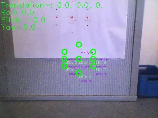
To get closer to my solution I estimated the pose in my testing environment. The translation vector-output and euler angel output refers to the inverse of [R|t]. The euler angels might not be displayed correct (they might be swaped or wrong, if we take order into account) because I compute it with the convetional (I assume refering to the airplane coordinate system) equations, using an open-cv coordinate system. (The computation happens in the class Pose which I will attach). But anyways even the translation vector (of the inverse) appeard to be wrong (in my simple test).
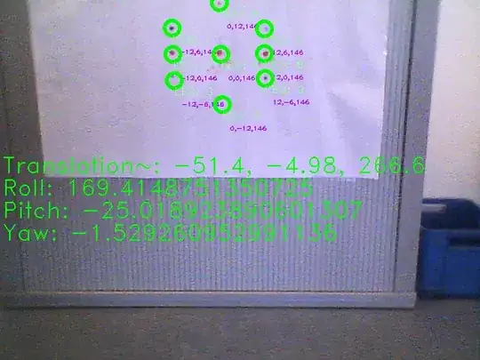
In one test with that Image I had a roll (which might be pitch in airplane coordinates) of 30° and a translation upwards of 50cm. That appeard to be more reasonable. So I assumed because my points are coplanar, I might get ambiguous results. So I realized an other test with a point which changed in the Z-Axis. But with this test even the projection failed. 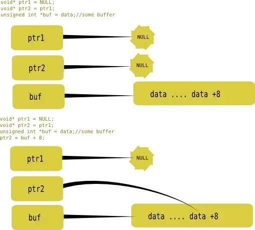
For solvePnP I tried all different solving-algorithm-flags and different parameters for the ransac algorithm.
Maybe you can somehow help me to find my mistake, or showing me a good path to solve my initial problem. I am going to attach also my debugging source-code with many println statements and the debugging images. This code contains my point measurements.
Thanks for your help in advance.
Class Main.java:
Class Pose.java:
0.png

1.png

EDIT 22.03.2015: Finally I have been able to find mistakes I made.
- I modified a Mat object in a for-loop, because OpenCV works a lot with call by reference, and I was not careful enough here. So the tvec and rvec for the reprojection were not right.
- One of my points in the testing environment had (in the image coordinates), was tagged wrong due to an axis-direction confusion.
So my approach in general was right. I am not receiving at least (often) valid reprojections in my test-dataset.
Unfortunately the OpenCV PnP algorithms: "ITERATIVE, P3P, EPNP" return various results, and even with using a very unaccurate but close intrinsic guess, the results are only sometimes correct. The P3P algorithm is supposed to provide 3 solutions, but OpenCV only provides one. EPNP is supposed to return good results, but with EPNP OpenCV returns the worst results, evaluated from my human obersation.
The problem now is, how to filter the inaccurate values or ensure the OpenCV function returns valid ones. (Maybe I shuold modify the native code to receive 3 solutions for PnP).
The compressed images here (37MB), do show my current results (with the ITERATIVE PnP-Solver) , with an intrinsic guess of zero rotation and 75 cm upwards. The print-out has an x-axis foreward, y-axis to the left and z-down, and corrosponding roll, pitch, and yaw angles.