4

Say I want to construct a 3D cubic Bézier curve, and I already have both end-points, and the direction (normal vector) for both control points. How can I choose the distance of both control points to their respective end-points in order to make the curve as 'nicely rounded' as possible?

To formalize 'nicely rounded': I think that means maximizing the smallest angle between any two segments in the curve. For example, having end-points (10, 0, 0) and (0, 10, 0) with respective normal vectors (0, 1, 0) and (1, 0, 0) should result in a 90° circular arc. For the specific case of 2D circular arcs, I've found articles like this one. But I haven't been able to find anything for my more general case.

too big     too small     just right

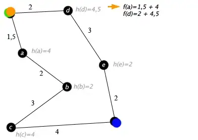
(Note that these images are just to illustrate the 'roundness' concept. My curves are not guaranteed to be plane-aligned. I may replace the images later to better illustrate that point.)

This is a question of aesthetics, and if the real solution is unknown or too complicated, I would be happy with a reasonable approximation. My current approximation is too simplistic: choosing half the distance between the two end-points for both control point distances. Someone more familiar with the math will probably be able to come up with something better.

(PS: This is for open-source software, and I would be happy to give credit on GitHub.)

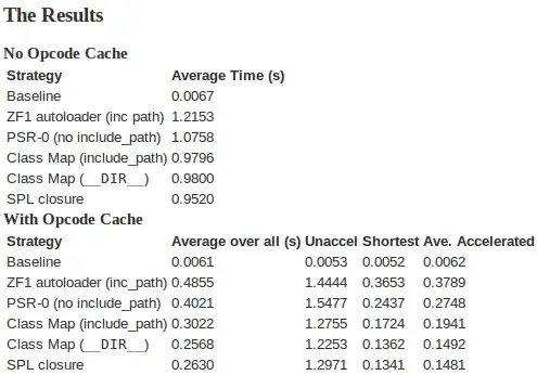
Edit: Here are some other images to illustrate a 3D case (jsfiddle):

bad     good

Edit 2: Here's a screenshot of an unstable version of ApiNATOMY to give you an idea of what I'm trying to do. I'm creating 3D tubes to represent blood-vessels, connecting different parts of an anatomical schematic:

ApiNATOMY with 3D blood-vessels

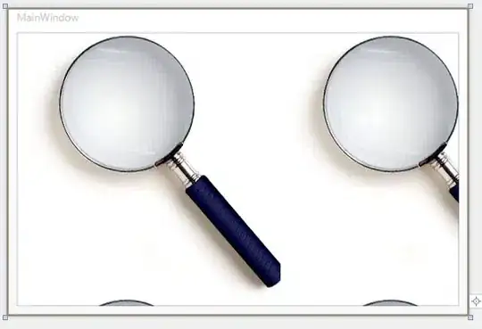
(They won't let me put in a jsfiddle link if I don't include code...)
mhelvens
  • 4,225
  • 4
  • 31
  • 55
  • I'm voting to close this question as off-topic because this is a math question belonging on the math.stackexchange – Rob May 24 '15 at 14:53
  • @Rob: There's a fine line between math and computer science. And I've seen [plenty](http://stackoverflow.com/questions/16052689/how-to-find-intersection-points-between-two-cubic-bezier-curve) of [questions](http://stackoverflow.com/questions/2742610/closest-point-on-a-cubic-bezier-curve) like [this](http://stackoverflow.com/questions/4148831/how-to-offset-a-cubic-bezier-curve) on [SO](http://stackoverflow.com/questions/404861/calculation-of-cubic-b%C3%A9zier-with-known-halfway-point). I found those while searching for an answer to my own question. – mhelvens May 24 '15 at 14:57
  • Also, I think I'll find answers from fellow programmers easier to understand than answers from mathematicians. (That said, if it must go, can it not be *moved* to math.stackexchange?) – mhelvens May 24 '15 at 14:59
  • I feel SO can show you how to code your problem but the math behind it belongs on the other exchange. I agree it should be moved, not closed, but there is no option for me to post it as that. – Rob May 24 '15 at 15:00
  • The math answer for this question will be almost entirely useless to a programmer. This question should stay right where it is, with a programmer's answer, not a mathematician's. The mathematician will give formulae that a programmer than *still* needs to simplify into steps that make sense for a computer. – Mike 'Pomax' Kamermans May 25 '15 at 04:13
  • That said, you're talking about 3D curves, why are you showing 2D images? Are your normals plane-aligned, or completely freeform? – Mike 'Pomax' Kamermans May 25 '15 at 04:23
  • @Mike'Pomax'Kamermans: Completely freeform. I am only using 2D images because they were easier to create. They were just to illustrate the 'roundness' concept. – mhelvens May 25 '15 at 07:04
  • Your latest update highly suggests you asked an [XY question](https://meta.stackexchange.com/questions/66377/what-is-the-xy-problem) (i.e. you have a problem, think of a solution, then ask about how to do that solution instead of asking how to solve the original problem). You can pretty trivially build these curves by building 3D [Catmull-Rom curves](http://stackoverflow.com/a/30431099/740553) through all points you know your curves need to pass through, which you know because you know which spots need connecting. (link is for building 2D C-R, 3D is a trivial extension) – Mike 'Pomax' Kamermans May 26 '15 at 20:00
  • @Mike'Pomax'Kamermans: I think you're probably right. :-) Just asking the 'higher level question' felt a bit... lazy. Like I'm asking someone else to do the work for me. But I'm going to have a good look at your link, and at Catmull-Rom in general. Thanks! – mhelvens May 26 '15 at 21:03

3 Answers3

1

What you are basically asking is to have curvature over the spline as constant as possible.

A curve with constant curvature is just a circular arc, so it makes sense to try to fit such an arc to your input parameters. In 2D, this is easy: construct the line which goes through your starting point and is orthogonal to the desired direction vector. Do the same for the ending point. Now intersect these two lines: the result is the center of the circle which passes through the two points with the desired direction vectors.

In your example, this intersection point would just be (0,0), and the desired circular arc lies on the unit circle.

So this gives you a circular arc, which you can either use directly or use the approximation algorithm which you have already cited.

This breaks down when the two direction vectors are collinear, so you'd have to fudge it a bit if this ever comes up. If they point at each other, you can simply use a straight line.

In 3D, the same construction gives you two planes passing through the end points. Intersect these, and you get a line; on this line, choose the point which minimizes the sum of squared distances to the two points. This gives you the center of a sphere which touches both end points, and now you can simply work in the plane spanned by these three points and proceed as in 2D.

cfh
  • 4,576
  • 1
  • 24
  • 34
  • You're oversimplifying the problem, I'm afraid. *"the result is the center of the circle which passes through the two points"* - this is only true when the direction vectors 'mirror each other', which is [not always the case](http://www.webreference.com/dlab/9902/f1.gif). In 3D, things get even more complicated. You could easily end up with a 3D curve that does not fit on one plane. – mhelvens May 24 '15 at 17:28
  • @mhelvens: That is true and I overlooked that. In the 2D case you mentioned, one would have to fit two circles on the respective normals, but with the same distance from their respective endpoints, and so that they just touch. This would give you the desired curvatures. – cfh May 25 '15 at 15:54
0

For the special case where your two end points and the two known normal vector for the control points happen to make the Bezier curve a planar one, then basically you are looking for a cubic Bezier curve that can well approximate a circular arc. For this special case, you can set the distance (denoted as L) between the control point and their respective end point as L = (4/3)*tan(A/4) where A is the angle of the circular arc.

For the general 3D case, perhaps you can apply the same formula as:

  • compute the angle between the two normal vectors.
  • use L=(4/3)*tan(A/4) to decide the location of your control points.
fang
  • 3,473
  • 1
  • 13
  • 19
  • This isn't actually true. That `L` applies only to the first control point, the second control point has a [rather more elaborate function](http://pomax.github.io/bezierinfo/#circles_cubic). – Mike 'Pomax' Kamermans May 25 '15 at 04:22
  • If the distance between the second control point and the end point has a "more elaborate" function, then the approximating Bezier curve is no longer symmetric to the bisector of the circular arc being approximated. Not really sure that will be a good approximation at all. – fang May 25 '15 at 05:05
  • sorry, I misread; but just knowing that the endpoint is 4/3*tan(phi/4) does not really help the original poster figure out what the functions for the control points *are*, which appears to be the actual question being asked, so there's information missing from this answer (as a programming question, that's necessary information. As a maths answer, this answer would work, but this isn't mathexchange. Stackoverflow audience cannot be expected to figure the math out from this hint) – Mike 'Pomax' Kamermans May 25 '15 at 05:40
  • It will be rare that the curve is planar. But even if we stick to that case, I don't understand why both you and cfh are talking about approximating a *circular arc*, when there are clearly [cases](http://www.webreference.com/dlab/9902/f1.gif) where this seems... questionable? – mhelvens May 25 '15 at 09:24
  • I agree that there are cases where the Bezier curve is clearly not anywhere close to a circular arc. But whatever formula that you used to determine the distance between the control point and their respective end point, this formula will need to work well when the Bezier curve has become a circular arc approximation (such as the example depicted by your pictures). This is the reason that I suggested using the (4/3)*tan(A/4) formula in the first place. If it also works for 3D cases in general, you get your answer. If it does not, perhaps some modification can be done from that formula. – fang May 25 '15 at 18:01
  • It's certainly a clue to the final answer. :-) – mhelvens May 25 '15 at 18:46
0

if your normals are aligned in a plane

What you're basically doing here is creating an elliptical arc, in 3D, where the "it's in 3D" part is completely irrelevant, since it's just a 2D curve, rotated/translated to sit in your 3D space. So let's just solve the 2D case, and then the RT is entirely up to you.

Creating the "perfect" cubic Bezier between two points on an arc comes with limitations. You basically can't create good looking arcs that span more than a quarter circle. So, with that said: your start and end point normals give you a 2D angle between your normal vectors, which is the same angle as between your start and end tangents (since normals are perpendicular to tangents). So, let's:

  1. align our curve so that the tangent at the start is 0
  2. plug the angle between tangents into the formula given in the section on Circle approximation in the Primer on Bezier curves. This is basically just dumb "implementing the formula for c1x/c1y/c2x/c2y as a function that takes an angle as argument, and spits out four values as c1(x,y) and c2(x,y) coordinats".
  3. There is no step 3, we're done.

After step 2, you have your control points in 2D to create the most circular arc between a start and end point. Now you just need to scale/rotate/translate it in 3D so that it lines up with where you needed your start and end point to begin with.

if your normals are not aligned in a plane

Now we have a problem, although one that we can deal with by treating the dimensions as separate things entirely. Instead of creating a single 2D curve, we're going to create three: one that's the X/Y projection, one that's the X/Z projection, and one that's the Y/Z projection. For all three of these, we're going to abstract the control points in exactly the same way as before, and then we simply take the projective control points (three for each control point), and then go "okay, we now have X, Y, and Z projective coordinates. That means we have (X,Y,Z) coordinates", and done again.

Mike 'Pomax' Kamermans
  • 49,297
  • 16
  • 112
  • 153
  • Interesting. I'm not sure I understand after my first read-through, but I'll have a closer look soon! – mhelvens May 25 '15 at 07:41
  • also note that this approach is for when your start and end tangents *allow* for a circular arc. As Fang points out, there are also "S" curvatures that are not covered by this approach. – Mike 'Pomax' Kamermans May 25 '15 at 16:15
  • Ah. So that's why I didn't understand after my first read-through. :-) The other two answers are also assuming a circular arc. But that's only the answer in the very specific case where the two direction vectors 'mirror each other' to allow for a circle. I guess I can only blame my overly simplistic example. I'll fix that shortly. – mhelvens May 25 '15 at 18:36
  • Note that in a lot of cases, this will work fine, *as long as* the projections allow for circular arcs. Things only go wrong is you have normals that are not like the images you added to your original question. For instance, a shape like in http://stackoverflow.com/a/25458216/740553, which projects as arc-approximatable on the XY plane, but projects as "S" on XZ and YZ – Mike 'Pomax' Kamermans May 25 '15 at 20:23
  • Unfortunately, S like shapes will be common in my application. Nonetheless, your projection approach is a valuable insight. – mhelvens May 26 '15 at 07:39
  • "S" shapes are caused by specific sets of (tangent/position) pairs for the start and end point, as well as the placement of the control points, so a start/end pair that *can* lead to an "S" curve does not necessarily do so depending on how far away you place the control points, which is an aesthetic consideration. What do you want to do with those kind of points? (maybe worth describing in the original question too, so it's possible for everyone to cover that case in their answers?) – Mike 'Pomax' Kamermans May 26 '15 at 15:45
  • I think that given start/end-point *positions* and control point *directions*, if it can be an "S", it's going to be an "S". Or am I missing something? Maybe I should explicitly mention that the control point distance may not be negative. - I'll create a screenshot of the kind of final constructions I'm creating. Good idea. – mhelvens May 26 '15 at 16:54
  • Technical incorrectness: both the start and control points are coordinates, i.e. positions. They are not vectors (i.e. directions). However, the tangents at the start and end points are wholy defined by the *position* of the control points. As for ruling out negative distance, I'm not sure what you mean with that mostly because distance cannot be negative (it's always a positive number, or zero), so you probably want to explain what kind of vectors are allowed while steering clear of those terms. – Mike 'Pomax' Kamermans May 26 '15 at 19:55
  • Yes, using absolute coordinates for control points is standard. Now let's consider a single control point *A* (belonging to an end point *E*). You can also represent it with a vector *R* so that *A = E + R*. Going one step further, you can represent it with a normal vector *D* indicating direction, and a scalar *d* indicating distance, so that *R = d × D*. Now, in the problem I'm trying to solve, *E* and *D* are given, and I need to find an optimal value for the scalar *d*. ----- Sorry if this wasn't clear from the original question. – mhelvens May 26 '15 at 20:54