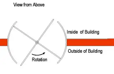
As you are unable to define what exactly is upper/lower arc then I will assume you cut the ellipse in halves by horizontal line going through the ellipse's middle point. If that is not the case then you have to adapt this on your own... Ok now how to do it:
binarize image
As you provide JPG the colors are distorted so there is more then just black and white
thin the border to 1 pixel
Fill the inside with white and then recolor all white pixels not neighboring any black pixels to some unused or black color. There are many other variation how to achieve this...
find the bounding box
search all pixels and remember min,max x,y coordinates of all white pixels. Let call them x0,y0,x1,y1.
compute center of ellipse
simply find middle point of bounding box
cx=(x0+x1)/2
cy=(y0+y1)/2
count the pixels for each elliptic arc
have counter for each arc and simply increment upper arc counter for any white pixel that have y<=cy and lower if y>=cy. If your coordinate system is different then the conditions can be reverse.
find ellipse parameters
simply find white pixel closest to (cx,cy) this will be endpoint of minor semi-axis b let call it (bx,by). Also find the most far white pixel to (cx,cy) that will be the major semi axis endpoint (ax,ay). The distances between them and center will give you a,b and their position substracted by center will give you vectors with rotation of your ellipse. the angle can be obtained by atan2 or use basis vectors as I do. You can test ortogonality by dot product. There can be more then 2 points for closest and farest point. in that case you should find the middle of each group to enhance precision.
Integrate fitted ellipse
You need first to find angle at which the ellipse points are with y=cy then integrate ellipse between these two angles. The other half is the same just integrate angles + PI. To determine which half it is just compute point in the middle between angle range and decide according y>=cy ...
[Edit2] Here updated C++ code I busted for this:
    picture pic0,pic1,pic2;
        // pic0 - source
        // pic1 - output
    float a,b,a0,a1,da,xx0,xx1,yy0,yy1,ll0,ll1;
    int x,y,i,threshold=127,x0,y0,x1,y1,cx,cy,ax,ay,bx,by,aa,bb,dd,l0,l1;
    pic1=pic0;
    // bbox,center,recolor (white,black)
    x0=pic1.xs; x1=0;
    y0=pic1.ys; y1=0;
    for (y=0;y<pic1.ys;y++)
     for (x=0;x<pic1.xs;x++)
      if (pic1.p[y][x].db[0]>=threshold)
        {
        if (x0>x) x0=x;
        if (y0>y) y0=y;
        if (x1<x) x1=x;
        if (y1<y) y1=y;
        pic1.p[y][x].dd=0x00FFFFFF;
        } else pic1.p[y][x].dd=0x00000000;
    cx=(x0+x1)/2; cy=(y0+y1)/2;
    // fill inside (gray) left single pixel width border (thining)
    for (y=y0;y<=y1;y++)
        {
        for (x=x0;x<=x1;x++) if (pic1.p[y][x].dd)
            {
            for (i=x1;i>=x;i--) if (pic1.p[y][i].dd)
                {
                for (x++;x<i;x++) pic1.p[y][x].dd=0x00202020;
                break;
                }
            break;
            }
        }
    for (x=x0;x<=x1;x++)
        {
        for (y=y0;y<=y1;y++) if (pic1.p[y][x].dd) { pic1.p[y][x].dd=0x00FFFFFF; break; }
        for (y=y1;y>=y0;y--) if (pic1.p[y][x].dd) { pic1.p[y][x].dd=0x00FFFFFF; break; }
        }
    // find min,max radius (periaxes)
    bb=pic1.xs+pic1.ys; bb*=bb; aa=0;
    ax=cx; ay=cy; bx=cx; by=cy;
    for (y=y0;y<=y1;y++)
     for (x=x0;x<=x1;x++)
      if (pic1.p[y][x].dd==0x00FFFFFF)
        {
        dd=((x-cx)*(x-cx))+((y-cy)*(y-cy));
        if (aa<dd) { ax=x; ay=y; aa=dd; }
        if (bb>dd) { bx=x; by=y; bb=dd; }
        }
    aa=sqrt(aa); ax-=cx; ay-=cy;
    bb=sqrt(bb); bx-=cx; by-=cy;
    //a=float((ax*bx)+(ay*by))/float(aa*bb);    // if (fabs(a)>zero_threshold) not perpendicular semiaxes

    // separate/count upper,lower arc by horizontal line
    l0=0; l1=0;
    for (y=y0;y<=y1;y++)
     for (x=x0;x<=x1;x++)
      if (pic1.p[y][x].dd==0x00FFFFFF)
        {
        if (y>=cy) { l0++; pic1.p[y][x].dd=0x000000FF; } // red
        if (y<=cy) { l1++; pic1.p[y][x].dd=0x00FF0000; } // blue
        }
    // here is just VCL/GDI info layer output so you can ignore it...

    // arc separator axis
    pic1.bmp->Canvas->Pen->Color=0x00808080;
    pic1.bmp->Canvas->MoveTo(x0,cy);
    pic1.bmp->Canvas->LineTo(x1,cy);

    // draw analytical ellipse to compare
    pic1.bmp->Canvas->Pen->Color=0x0000FF00;
    pic1.bmp->Canvas->MoveTo(cx,cy);
    pic1.bmp->Canvas->LineTo(cx+ax,cy+ay);
    pic1.bmp->Canvas->MoveTo(cx,cy);
    pic1.bmp->Canvas->LineTo(cx+bx,cy+by);
    pic1.bmp->Canvas->Pen->Color=0x00FFFF00;
    da=0.01*M_PI;   // dash step [rad]
    a0=0.0;         // start
    a1=2.0*M_PI;    // end
    for (i=1,a=a0;i;)
        {
        a+=da; if (a>=a1) { a=a1; i=0; }
        x=cx+(ax*cos(a))+(bx*sin(a));
        y=cy+(ay*cos(a))+(by*sin(a));
        pic1.bmp->Canvas->MoveTo(x,y);
        a+=da; if (a>=a1) { a=a1; i=0; }
        x=cx+(ax*cos(a))+(bx*sin(a));
        y=cy+(ay*cos(a))+(by*sin(a));
        pic1.bmp->Canvas->LineTo(x,y);
        }

    // integrate the arclengths from fitted ellipse
    da=0.001*M_PI;      // integration step [rad] (accuracy)
    // find start-end angles
    ll0=M_PI; ll1=M_PI;
    for (i=1,a=0.0;i;)
        {
        a+=da; if (a>=2.0*M_PI) { a=0.0; i=0; }
        xx1=(ax*cos(a))+(bx*sin(a));
        yy1=(ay*cos(a))+(by*sin(a));
        b=atan2(yy1,xx1);
        xx0=fabs(b-0.0); if (xx0>M_PI) xx0=2.0*M_PI-xx0;
        xx1=fabs(b-M_PI);if (xx1>M_PI) xx1=2.0*M_PI-xx1;
        if (ll0>xx0) { ll0=xx0; a0=a; }
        if (ll1>xx1) { ll1=xx1; a1=a; }
        }
    // [upper half]
    ll0=0.0;
    xx0=cx+(ax*cos(a0))+(bx*sin(a0));
    yy0=cy+(ay*cos(a0))+(by*sin(a0));
    for (i=1,a=a0;i;)
        {
        a+=da; if (a>=a1) { a=a1; i=0; }
        xx1=cx+(ax*cos(a))+(bx*sin(a));
        yy1=cy+(ay*cos(a))+(by*sin(a));
        // sum arc-line sizes
        xx0-=xx1; xx0*=xx0;
        yy0-=yy1; yy0*=yy0;
        ll0+=sqrt(xx0+yy0);
//      pic1.p[int(yy1)][int(xx1)].dd=0x0000FF00; // recolor for visualy check the right arc selection
        xx0=xx1; yy0=yy1;
        }
    // lower half
    a0+=M_PI; a1+=M_PI; ll1=0.0;
    xx0=cx+(ax*cos(a0))+(bx*sin(a0));
    yy0=cy+(ay*cos(a0))+(by*sin(a0));
    for (i=1,a=a0;i;)
        {
        a+=da; if (a>=a1) { a=a1; i=0; }
        xx1=cx+(ax*cos(a))+(bx*sin(a));
        yy1=cy+(ay*cos(a))+(by*sin(a));
        // sum arc-line sizes
        xx0-=xx1; xx0*=xx0;
        yy0-=yy1; yy0*=yy0;
        ll1+=sqrt(xx0+yy0);
//      pic1.p[int(yy1)][int(xx1)].dd=0x00FF00FF; // recolor for visualy check the right arc selection
        xx0=xx1; yy0=yy1;
        }
    // handle if the upper/lower parts are swapped
    a=a0+0.5*(a1-a0);
    if ((ay*cos(a))+(by*sin(a))<0.0) { a=ll0; ll0=ll1; ll1=a; }
    // info texts
    pic1.bmp->Canvas->Font->Color=0x00FFFF00;
    pic1.bmp->Canvas->Brush->Style=bsClear;
    x=5; y=5; i=16; y-=i;
    pic1.bmp->Canvas->TextOutA(x,y+=i,AnsiString().sprintf("center = (%i,%i) px",cx,cy));
    pic1.bmp->Canvas->TextOutA(x,y+=i,AnsiString().sprintf("a = %i px",aa));
    pic1.bmp->Canvas->TextOutA(x,y+=i,AnsiString().sprintf("b = %i px",bb));
    pic1.bmp->Canvas->TextOutA(x,y+=i,AnsiString().sprintf("upper = %i px",l0));
    pic1.bmp->Canvas->TextOutA(x,y+=i,AnsiString().sprintf("lower = %i px",l1));
    pic1.bmp->Canvas->TextOutA(x,y+=i,AnsiString().sprintf("upper`= %.3lf px",ll0));
    pic1.bmp->Canvas->TextOutA(x,y+=i,AnsiString().sprintf("lower`= %.3lf px",ll1));
    pic1.bmp->Canvas->Brush->Style=bsSolid;
It use my own picture class with members:
xs,ys resolution of imagep[y][x].dd pixel access as 32bit unsigned integer as colorp[y][x].db[4] pixel access as 4*8bit unsigned integer as color channels
You can look at picture::p member as simple 2D array of
union color
    {
    DWORD dd; WORD dw[2]; byte db[4];
    int i; short int ii[2];
    color(){}; color(color& a){ *this=a; }; ~color(){}; color* operator = (const color *a) { dd=a->dd; return this; }; /*color* operator = (const color &a) { ...copy... return this; };*/
    };
int xs,ys;
color p[ys][xs];
Graphics::TBitmap *bmp; // VCL GDI Bitmap object you do not need this...
where each cell can be accessed as 32 bit pixel p[][].dd as 0xAABBGGRR or 0xAARRGGBB not sure now which. Also you can access the channels directly with p[][].db[4] as 8bit BYTEs.
The bmp member is GDI bitmap so bmp->Canvas-> access all the GDI stuff which is not important for you.
Here result for your second image:
- Gray horizontal line is the arc boundary line going through center
- Red,Blue are the arc halves (recolored during counting)
- Green are the semi-axes basis vectors
- Aqua dash-dash is analytical ellipse overlay to compare the fit.
As you can see the fit is pretty close (+/-1 pixel). The counted arc-lengths upper,lower are pretty close to approximated average circle half perimeter(circumference).
You should add a0 range check to decide if the start is upper or lower half because there is no quarantee which side of major axis this will find. The integration of both halves are almost the same and saturated around integration step 0.001*M_PI around 307.3 pixels per arc-length which is only 17 and 22 pixels difference from the direct pixel count which is even better then I anticipate due to aliasing ...
For more eccentric ellipses the fit is not as good but the results are still good enough: