3

I am using this code to generate sphere vertices and textures but as you can see in the image , when I rotate it I can see a dark band.

 for (int i = 0; i <= stacks; ++i)
    {
        float s = (float)i / (float) stacks;
        float theta = s * 2 * glm::pi<float>();

        for (int j = 0; j <= slices; ++j)
        {
            float sl = (float)j / (float) slices;
            float phi = sl * (glm::pi<float>());

            const float x = cos(theta) * sin(phi);
            const float y = sin(theta) * sin(phi);
            const float z = cos(phi);

            sphere_vertices.push_back(radius * glm::vec3(x, y, z));
            sphere_texcoords.push_back((glm::vec2((x + 1.0) / 2.0, (y + 1.0) / 2.0)));
        }
    }

    // get the indices

    for (int i = 0; i < stacks * slices + slices; ++i)
    {
        sphere_indices.push_back(i);
        sphere_indices.push_back(i + slices + 1);
        sphere_indices.push_back(i + slices);

        sphere_indices.push_back(i + slices + 1);
        sphere_indices.push_back(i);
        sphere_indices.push_back(i + 1);
    }

I can't figure a way to make it right whatever texture coordinates I used.

ball

Hmm.. If I use another image, then the mapping is different (and worst!)

ball2

vertex shader:

#version 330 core

layout (location = 0) in vec3 aPos;
layout (location = 1) in vec3 aTexCoord;

out vec4 vertexColor;
out vec2 TexCoord;

uniform mat4 model;
uniform mat4 view;
uniform mat4 projection;

void main()
{
    gl_Position = projection * view * model * vec4(aPos.x, aPos.y, aPos.z, 1.0);
    vertexColor = vec4(0.5, 0.2, 0.5, 1.0);
    TexCoord = vec2(aTexCoord.x, aTexCoord.y);
}

fragment shader:

#version 330 core
out vec4 FragColor;

in vec4 vertexColor;
in vec2 TexCoord;

uniform sampler2D sphere_texture;

void main()
{

    FragColor = texture(sphere_texture, TexCoord);
}

I am not using any lighting conditions.


If I use FragColor = vec4(TexCoord.x, TexCoord.y, 0.0f, 1.0f); in fragment shader (for debugging purposes) , I am receiving a nice sphere.

ball3

I am using this as texture:

texture

Spektre
  • 49,595
  • 11
  • 110
  • 380
George
  • 5,808
  • 15
  • 83
  • 160
  • What code path in the fragment shader is outputting black pixels? Is this a lighting calculation? I see the dark band is perpendicular to the lighting hot spot, as opposed to being situated geometrically equatorial. – Wyck Sep 09 '19 at 13:22
  • @Wyck:I uploaded vertex and fragment shaders, I am not using any light conditions. – George Sep 09 '19 at 13:25
  • OIC. There must either A) be a black pixel in your texture that got sampled, which suggests the TexCoord got set to the coordinates of that pixel. Maybe 0,0? Maybe negative that got clamped to 0,0? or B) you are using a border color, like `glTexParameterfv(GL_TEXTURE_2D, GL_TEXTURE_BORDER_COLOR, blackBorderColor);` and your texture coordinates are out of bounds. – Wyck Sep 09 '19 at 13:30
  • **For debugging purposes**, you can output a color that is a function of your texture coordinates rather than the sampled texture at those coordinates. One popular choice is mapping (u,v) to (red,green) as in `vec4(TexCoord.x, TexCoord.y, 0, 1)`. If they are out of bounds, you can scale them down a bit (rather than directly mapping them to the 0-1 range) so you can see what's going on. – Wyck Sep 09 '19 at 13:33
  • @Wyck:I used the colors from texcoords and it seems to run fine!It shoes a nice sphere.As for the `glTexParamater` , I only use `glTexParameteri(GL_TEXTURE_2D, GL_TEXTURE_WRAP_S, GL_REPEAT);` `glTexParameteri(GL_TEXTURE_2D, GL_TEXTURE_WRAP_T, GL_REPEAT);` `glTexParameteri(GL_TEXTURE_2D, GL_TEXTURE_MIN_FILTER, GL_LINEAR);` `glTexParameteri(GL_TEXTURE_2D, GL_TEXTURE_MAG_FILTER, GL_LINEAR);` – George Sep 09 '19 at 13:48
  • @Wyck:I am not using any `glTexParameterfv` or any `BORDER_COLOR` – George Sep 09 '19 at 13:49
  • I'd like to see side-by-side the colors-from-texcoord, next to the black band, from the same camera and orientation, and the texture itself. Can't tell if the black pixels are in your texture. In other words, what part of that last colors-from-textcoords image goes black when you switch to the texture? – Wyck Sep 09 '19 at 14:46
  • @Wyck: Sorry, I am not sure I understand your comment.The texture is just this [image](https://ibb.co/gVJdP7v) . No black pixels there. – George Sep 10 '19 at 07:02
  • common bug leading to similar bands are the texture crossing ... you know your texture coordinate is increasing like `0.0,0.1,0.2,...,0.9` but than you need to join with start `0.9,0.0` which will give you the entire texture in single band ... to avoid this you need to duplicate the first vertexes as last with texture coordinate `1.0` also in case you do not use `GL_WRAP_TO_EDGE` you need to rescale from `<0.0,1.0>` to ``. However your texture image suggest different texturing technique than standard rectangular mapping ... – Spektre Sep 10 '19 at 07:22
  • @Spektre:For the duplicate, you mean something like: `sphere_vertices.push_back(radius * glm::vec3(0, 0, 1));`? (because for i = 0 and j =0 , x, y, z are :0,0,1). And change the loops to for (int i = 0; i < stacks; ++i), for (int j = 0; j < slices; ++j) , instead of <=stacks? I tried it bust still getting the dark band although it has a good (with the image texture) gap inside. – George Sep 10 '19 at 08:03
  • hard to say as according to your comments you are not using rectangular texture mapping like this [Applying map of the earth texture a Sphere](https://stackoverflow.com/a/31804515/2521214) but some nonlinear mapping instead which you did not describe at all and disecting from code is too much for my lazyness. However looking at the texture you might have also lighting problems (the image is not uniformly lighted) but most likely you hit some accuracy barrier on the edge of the mapping (you know the slope goes to infinity with your style of mapping).... – Spektre Sep 10 '19 at 09:29
  • your style is more like [last equidistant example here](https://stackoverflow.com/a/32558700/2521214) but your texture does not have the same properties ... (mirroring back side instead?) .... – Spektre Sep 10 '19 at 09:32
  • @George: Aha! The answer is in your image! Thanks for linking it. (transparent pixels, and the circle doesn't fill the square) I'll post a detailed answer shortly. – Wyck Sep 10 '19 at 13:09
  • @Spektre:Thanks for your info on this and for the links! I realized that if I use a rectangle texture image , it maps ok! – George Sep 10 '19 at 14:11

2 Answers2

4

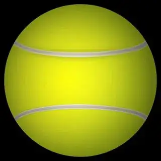
That image of the tennis ball that you linked reveals the problem. I'm glad you ultimately provided it.

enter image description here

Your image is a four-channel PNG with transparency (Alpha channel). There are transparent pixels all around the outside of the yellow part of the ball that have (R,G,B,A) = (0, 0, 0, 0), so if you're ignoring the A channel then (R, G, B), will be (0, 0, 0) = black.

Here are just the Red, Green, and Blue (RGB) channels:

enter image description here

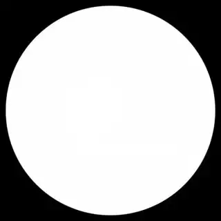
And here is just the Alpha (A) channel.

enter image description here

The important thing to notice is that the circle of the ball does not fill the square. There is a significant margin of 53 pixels of black from the extent of the ball to the edge of the texture. We can calculate the radius of the ball from this. Half the width is 1000 pixels, of which 53 pixels are not used. The ball's radius is 1000-53, which is 947 pixels. Or about 94.7% of the distance from the center to the edge of the texture. The remaining 5.3% of the distance is black.

Side note: I also notice that your ball doesn't quite reach 100% opacity. The yellow part of the ball has an alpha channel value of 254 (of 255) Meaning 99.6% opaque. The white lines and the shiny hot spot do actually reach 100% opacity, giving it sort of a Death Star look. ;)

To fix your problem, there's the intuitive approach (which may not work) and then there are two things that you need to do that will work. Here are a few things you can do:

Intuitive Solution:

This won't quite get you 100% there.

1) Resize the ball to fill the texture. Use image editing software to enlarge the ball to fill the texture, or to trim off the black pixels. This will just make more efficient use of pixels, for one, but it will ensure that there are useful pixels being sampled at the boundary. You'll probably want to expand the image to be slightly larger than 100%. I'll explain why below. 2) Remap your texture coordinates to only extend to 94.7% of the radius of the ball. (Similar to approach 1, but doesn't require image editing). This just uses coordinates that actually correspond to the image you provided. Your x and y coordinates need to be scaled about the center of the image and reduced to about 94.7%.

x2 = 0.5 + (x - 0.5) * 0.947;
y2 = 0.5 + (y - 0.5) * 0.947;

Suggested Solution:

This will ensure no more black.

3) Fill the "black" portion of your ball texture with a less objectionable colour - probably the colour that is at the circumference of the tennis ball. This ensures that any texels that are sampled at exactly the edge of the ball won't be linearly combined with black to produce an unsightly dark-but-not-quite-black band, which is almost the problem you have right now anyway. You can do this in two ways. A) Image editing software. Remove the transparency from your image and matte it against a dark yellow colour. B) Use the shader to detect pixels that are outside the image and replace them with a border colour (this is clever, but probably more trouble than it's worth.)

Different Texture Coordinates

The last thing you can do is avoid this degenerate texture mapping coordinate problem altogether. At the equator, you're not really sure which pixels to sample. The black (transparent) pixels or the coloured pixels of the ball. The discrete nature of square pixels, is fighting against the polar nature of your texture map. You'll never find the exact colour you need near the edge to produce a continuous, seamless map. Instead, you can use a different coordinate system. I hope you're not attached to how that ball looks, because let me introduce you to the equirectangular projection. It's the same projection that you can naively use to map the globe of the Earth to a typical rectangular map of the world you're likely familiar with where the north and south poles get all the distortion but the equatorial regions look pretty good.

Here's your image mapped to equirectangular coordinates:

enter image description here

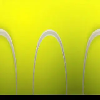
Notice that black bar at the bottom...we're onto something! That black bar is actually exactly what appears around the equator of your ball with your current texture mapping coordinate system. But with this coordinate system, you can see easily that if we just remapped the ball to fill the square we'd completely eliminate any transparent pixels at all.

It may be inconvenient to work in this coordinate system, but you can transform your image in Photoshop using Filter > Distort > Polar Coordinates... > Polar to Rectangular.

Sigismondo's answer already suggests how to adjust your texture mapping coordinates do this.

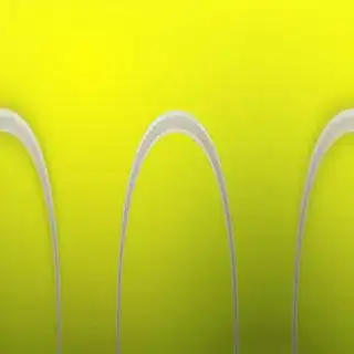
And finally, here's a texture that is both enlarged to fill the texture space, and remapped to equirectangular coordinates. No black bars, minimal distortion. But you'll have to use Sigismondo's texture mapping coordinates. Again, this may not be for you, especially if you're attached to the idea of the direct projection for your texture (i.e.: if you don't want to manipulate your tennis ball image and you want to use that projection.) But if you're willing to remap your data, you can rest easy that all the black pixels will be gone!

enter image description here

Good luck! Feel free to ask for clarifications.

Wyck
  • 10,311
  • 6
  • 39
  • 60
  • Ok!That makes sense now! Thanks a lot for your effort in this! I wasn't thinking the image properties at all. I was just thinking the code part only..(upv) – George Sep 10 '19 at 14:11
  • great analysis dude! I didn't expect you could map a circle onto a sphere (original code) - I assumed that the original image was "equirectangular" without seeing it - thinking it was the only way you could map a texture on a sphere. One question: with the original mapping the texture is going to be mapped "twice" (z-positive and z-negative have the same x,y coordinates). This alone let me think it was wrong. Is this king of approach reasonable and used in practice instead - except for the non linear mapping you have in this specific case I mean. – Sigi Sep 11 '19 at 08:40
  • 1
    @Sigismondo, You are right that it would be mapped twice. If the texture sits in the XY plane, then every point on the sphere with the same XY coordinates will get the same texture coordinates -- and for a sphere centered at the origin, there are always two points with the same XY (with the exception of the points on the Z=0 plane: a circle around the equator). This is called ***orthographic planar projection***. May I suggest referring to [this excellent set of diagrams](https://learn.foundry.com/modo/content/help/pages/shading_lighting/shader_items/projection_type_samples.html) – Wyck Sep 12 '19 at 13:15
0

I cannot test it, being the code incomplete, but from a rough look I have spotted this problem:

sphere_texcoords.push_back((glm::vec2((x + 1.0) / 2.0, (y + 1.0) / 2.0)));

The texture coordinates should not be evaluated from x and y, being:

const float x = cos(theta) * sin(phi);
const float y = sin(theta) * sin(phi);

but from the angles thta-phi, or stacks-slices. this could work better - untested:

sphere_texcoords.push_back(glm::vec2(s,sl));

being already defined:

float s = (float)i / (float) stacks;
float sl = (float)j / (float) slices;

Furthermore in your code you are using the first and the last "slices" of the sphere as the rest... Shouldn't they be treated differently? This seems quite odd to me - but I don't know whether your implementation is just a simpler one, working fine.

Compare with this explanation, for example: http://www.songho.ca/opengl/gl_sphere.html

Sigi
  • 4,826
  • 1
  • 19
  • 23
  • I used the `vec2(s, sl)` and I am receiving [this image](https://ibb.co/8NYz96p).As for the code in the link you gave me , I have already used it and it shows the same dark band. – George Sep 10 '19 at 06:57
  • 2
    I've found this interesting link: http://paulbourke.net/geometry/spherical/ – Sigi Sep 11 '19 at 10:53