26

I have a path made up of a list of 2D points. I want to turn these into a strip of triangles in order to render a textured line with a specified thickness (and other such things). So essentially the list of 2D points need to become a list of vertices specifying the outline of a polygon that if rendered would render the line. The problem is handling the corner joins, miters, caps etc. The resulting polygon needs to be "perfect" in the sense of no overdraw, clean joins, etc. so that it could feasibly be extruded or otherwise toyed with.

Are there any simple resources around that can provide algorithm insight, code or any more information on doing this efficiently?

I absolutely DO NOT want a full fledged 2D vector library (cairo, antigrain, OpenVG, etc.) with curves, arcs, dashes and all the bells and whistles. I've been digging in multiple source trees for OpenVG implementations and other things to find some insight, but it's all terribly convoluted.

I'm definitely willing to code it myself, but there are many degenerate cases (small segments + thick widths + sharp corners) that create all kinds of join issues. Even a little help would save me hours of trying to deal with them all.

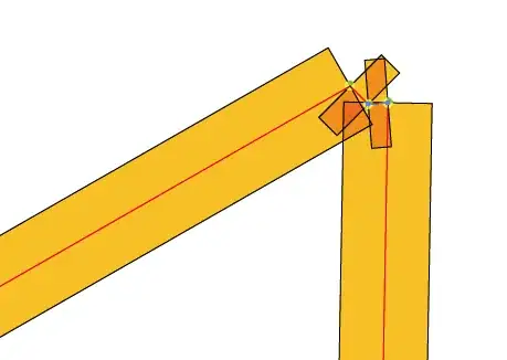
EDIT: Here's an example of one of those degenerate cases that causes ugliness if you were simply to go from vertex to vertex. Red is the original path. The orange blocks are rectangles drawn at a specified width aligned and centered on each segment.
Community
  • 1
  • 1
Patrick Hogan
  • 2,098
  • 4
  • 20
  • 28
  • I've been wanting this too. I fudged it in the prototype with simple boxes between the points, but it's going to have to be fixed eventually. Hopefully your question draws the right responses. Either way, get back to us and tell us what you eventually did. – Adam Davis Mar 26 '09 at 20:56
  • In response to your picture, You are not bisecting the angles, you are going perpendicular to your lines. – Neil N Mar 26 '09 at 22:02
  • Yes, I know. That's pre-whatever-join-algorithm-gets-applied. I'm just illustrating a problem case, not what happens when you actually apply something to it. – Patrick Hogan Mar 27 '09 at 13:10

9 Answers9

4

I just found this amazing work:

http://www.codeproject.com/Articles/226569/Drawing-polylines-by-tessellation

It seems to do exactly what you want, and its licence allows to use it even in commercial applications. Plus, the author did a truly great job to detail his method. I'll probably give it a shot at some point to replace my own not-nearly-as-perfect implementation.

Boris Dalstein
  • 7,015
  • 4
  • 30
  • 59
  • While this link may answer the question, it is better to include the essential parts of the answer here and provide the link for reference. Link-only answers can become invalid if the linked page changes. – AstroCB Oct 28 '14 at 01:26
  • 1
    @AstroCB: fair enough, but the question the OP is asking is actually an extremely difficult question. In fact, it is pretty much an open research problem. There is no way a good answer would fit well in Stack Overlow. A link to a pretty good resource tackling the problem is I think a very relevant and helpful answer, and in this case little point in trying to summarize the method here, which I have no time anyway."-1" means "the answer is not useful". I fail to see how pointing to a good resource is not useful. It is not perfect, indeed, but actually useful. – Boris Dalstein Nov 12 '14 at 00:29
  • For the record, I did not downvote (see [here](http://i.stack.imgur.com/gv7cN.png)), but I'd like to point you to [this question](http://meta.stackexchange.com/questions/225370/your-answer-is-in-another-castle-when-is-an-answer-not-an-answer), which lays out Stack Exchange policy for these types of answers. The comment is an auto-generated one based on an action I took in a review queue, which is where this post ended up after someone (presumably the same person who downvoted it) flagged it as "low quality." – AstroCB Nov 12 '14 at 00:40
  • @AstroCB OK, thx for the clarification :) Note that my answer is still significantly longer and gives some context, compared to those given in the guidelines for "link answers". Anyway, guidelines are what they are: guidelines. Not rules. – Boris Dalstein Nov 12 '14 at 00:51
  • I am working on line rendering about a week now with the same problems as OP. While the linked article/project (Vase renderer) is pretty nice it STILL has overdraw in tight corners. So far i found no way around this problem. – SleepProgger Feb 13 '20 at 20:52
4

Oh well - I've tried to solve that problem myself. I wasted two month on a solution that tried to solve the zero overdraw problem. As you've already found out you can't deal with all degenerated cases and have zero overdraw at the same time.

You can however use a hybrid approach:

Write yourself a routine that checks if the joins can be constructed from simple geometry without problems. To do so you have to check the join-angle, the width of the line and the length of the joined line-segments (line-segments that are shorter than their width are a PITA). With some heuristics you should be able to sort out all the trivial cases.

I don't know how your average line-data looks like, but in my case more than 90% of the wide lines had no degenerated cases.

For all other lines:

You've most probably already found out that if you tolerate overdraw, generating the geometry is a lot easier. Do so, and let a polygon CSG algorithm and a tesselation algorithm do the hard job.

I've evaluated most of the available tesselation packages, and I ended up with the GLU tesselator. It was fast, robust, never crashed (unlike most other algorithms). It was free and the license allowed me to include it in a commercial program. The quality and speed of the tesselation is okay. You will not get delaunay triangulation quality, but since you just need the triangles for rendering that's not a problem.

Since I disliked the tesselator API I lifted the tesselation code from the free SGI OpenGL reference implementation, rewrote the entire front-end and added memory pools to get the number of allocations down. It took two days to do this, but it was well worth it (like factor five performance improvement). The solution ended up in a commercial OpenVG implementation btw :-)

If you're rendering with OpenGL on a PC, you may want to move the tesselation/CSG-job from the CPU to the GPU and use stencil-buffer or z-buffer tricks to remove the overdraw. That's a lot easier and may be even faster than CPU tesselation.

Nils Pipenbrinck
  • 83,631
  • 31
  • 151
  • 221
2

A simple method off the top of my head.

Bisect the angle of each 2d Vertex, this will create a nice miter line. Then move along that line, both inward and outward, the amount of your "thickness" (or thickness divided by two?), you now have your inner and outer polygon points. Move to the next point, repeat the same process, building your new polygon points along the way. Then apply a triangualtion to get your render-ready vertexes.

Neil N
  • 24,862
  • 16
  • 85
  • 145
  • I had that part figured out. :) The problem is there are a few cases where those vertices would generate overlapping triangles. Basically I need to eliminate vertices that would end up causing weird artifacts. – Patrick Hogan Mar 26 '09 at 21:14
  • I dont think you understood the bisection part. – Neil N Mar 26 '09 at 21:25
  • I do understand, but it still produces ugliness. See example image added to post. Each side of that line poses a different problem. – Patrick Hogan Mar 26 '09 at 22:04
  • No, your picture is using perpendicular lines, not bisections. A bisection is the halfway point between an angle. If your base line forms a 90 degree angle, your bisection is at 45. get it? – Neil N Mar 26 '09 at 22:08
1

I ended up having to get my hands dirty and write a small ribbonizer to solve a similar problem.

For me the issue was that I wanted fat lines in OpenGL that did not have the kinds of artifacts that I was seeing with OpenGL on the iPhone. After looking at various solutions; bezier curves and the like - I decided it was probably easiest to just make my own. There are a couple of different approaches.

One approach is to find the angle of intersection between two segments and then move along that intersection line a certain distance away from the surface and treat that as a ribbon vertex. I tried that and it did not look intuitive; the ribbon width would vary.

Another approach is to actually compute a normal to the surface of the line segments and use that to compute the ideal ribbon edge for that segment and to do actual intersection tests between ribbon segments. This worked well except that for sharp corners the ribbon line segment intersections were too far away ( if the inter-segment angle approached 180' ).

I worked around the sharp angle issue with two approaches. The Paul Bourke line intersection algorithm ( which I used in an unoptimized way ) suggested detecting if the intersection was inside of the segments. Since both segments are identical I only needed to test one of the segments for intersection. I could then arbitrate how to resolve this; either by fudging a best point between the two ends or by putting on an end cap - both approaches look good - the end cap approach may throw off the polygon front/back facing ordering for opengl.

See http://paulbourke.net/geometry/lineline2d/

See my source code here : https://gist.github.com/1474156

Mario S
  • 11,715
  • 24
  • 39
  • 47
  • 1
    One of my pet peeves with PostScript, and unfortunately other drawing paradigms follow its lead, is that miter corners are either drawn as a perfect miter (if it doesn't extend out past the miter limit) or as a bevel. I wonder why the miter limit couldn't have been used as a point to "chop off" the miter corner. – supercat Jun 08 '13 at 18:58
0

In my case I could afford to overdraw. I just drow circles with radius = width/2 centered on each of the polyline's vertices.

Artifacts are masked this way, and it is very easy to implement, if you can live with "rounded" corners and some overdrawing.

kikito
  • 51,734
  • 32
  • 149
  • 189
0

From your image it looks like that you are drawing box around line segments with FILL on and using orange color. Doing so is going to create bad overdraws for sure. So first thing to do would be not render black border and fill color can be opaque.

Why can't you use GL_LINES primitive to do what you intent to do? You can specify width, filtering, smoothness, texture anything. You can render all vertices using glDrawArrays(). I know this is not something you have in mind but as you are focusing on 2D drawing, this might be easier approach. (search for Textured lines etc.)

Ketan
  • 1,017
  • 8
  • 17
0

I think I'd reach for a tessellation algorithm. It's true that in most case where these are used the aim is to reduce the number of vertexes to optimise rendering, but in your case you could parameterise to retain all the detail - and the possibility of optimising may come in useful.

There are numerous tessellation algorithms and code around on the web - I wrapped up a pure C on in a DLL a few years back for use with a Delphi landscape renderer, and they are not an uncommon subject for advanced graphics coding tutorials and the like.

Cruachan
  • 15,733
  • 5
  • 59
  • 112
0

I'm interested in this too, since I want to perfect my mapping application's (Kosmos) drawing of roads. One workaround I used is to draw the polyline twice, once with a thicker line and once with a thinner, with a different color. But this is not really a polygon, it's just a quick way of simulating one. See some samples here: http://wiki.openstreetmap.org/wiki/Kosmos_Rendering_Help#Rendering_Options

I'm not sure if this is what you need.

Igor Brejc
  • 18,714
  • 13
  • 76
  • 95
0

See if Delaunay triangulation can help.

GSerg
  • 76,472
  • 17
  • 159
  • 346