0

I have a graph like this:

graph image

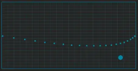
And I want to be able to convert the position of P1 aka the ball you can drag around to scale with different starting and ending points on my screen.

I esentially want to make it so that the curve dot is around the same position no matter where the starting and ending positions are for the curve

So if I had a different points on my screen it would look the same as the graph

This is what I tried to do but it didn't work

function bezier.scale(startingPosition : Vector2, endingPosition : Vector2)
        local screenSize = workspace.CurrentCamera.ViewportSize
        local lengthX = (endingPosition.X - startingPosition.X)
        local lengthY = (endingPosition.Y - startingPosition.Y)
        
        local screenRelativeX = (screenSize.X - startingPosition.X) + lengthX
        local screenRelativeY = (screenSize.Y - startingPosition.Y) + lengthY
        local scaleX = (screenRelativeX / graphBackground.Size.X.Offset)
        local scaleY = (screenRelativeY  / graphBackground.Size.Y.Offset) 

        local x = (bezierPoint.Position.X.Offset * scaleX) 
        local y = (bezierPoint.Position.Y.Offset * scaleY) 

        return Vector2.new(x, y)
      end 
Require
  • 41
  • 4
  • can you add sample input and wanted output as its not clear what you are trying to achieve ... – Spektre Jun 06 '22 at 06:58
  • As in, lets say my graph coordinate for the draggable dot is like X:250, Y:50 and the size of the graph is X:440 Y:240 I want to make it so that the dot is around the same position no matter where the starting and ending positions are for the curve – Require Jun 06 '22 at 07:05
  • That still not make any sense ... what exactly is your input? Bezier involves 3 or more points depend on degree and piecewiseness, ... plus your draggable point ... what exactly you want to do with the dragable point? drag its x and compute y so it belongs to the Bezier curve? or what ? your comment `I want to make it so that the dot is around the same position no matter where the starting and ending positions are for the curve` implies your dragabble point is not moving at all ... or you want to move the bezier curve the same way as the draggable point ? how does scalling come in? – Spektre Jun 06 '22 at 08:03
  • Im saying like, lets say my mouse is the starting position and some random area on my screen is the ending position. I want to my mouse to follow the same curve as shown on the graph. Howerver, the distance between my mouse and the target isn't always going to be the same so therefore I want to know how to scale it so I can emulate the same curve no matter where it is and what the distance between the points are. – Require Jun 06 '22 at 08:07
  • So mouse just selects the start point and has nothing to do with movement ... and the endpoint is known ahead? so you have some bezier path with known start end point and just want to construct affine transform that maps it to your mouse position and "random" endpoint ? – Spektre Jun 06 '22 at 08:11
  • Yeah I think I want to do what you are saying, basically just use the visualized curve for mouse movement. But I cant figure how to convert everything over. – Require Jun 06 '22 at 08:30
  • I added answer ... if you are not familiar with vector math notation look at the link at the end of answer ... in there near end of that answer is vector math implemented element wise (rewritten to `x,y,z`) – Spektre Jun 06 '22 at 08:47
  • 1
    Can you also please update your post so that all the details talked about in these comments are [also just in your post](/help/how-to-ask), because right now the post itself lacks enough detail to answer on its own. – Mike 'Pomax' Kamermans Jun 06 '22 at 17:43

1 Answers1

0

so your input is 4 2D points ... first 2 points p0,p1 are constant refer to your BEZIER start and end points and the next 2 q0,q1 are start and end point for your animation. So you want affine transform mapping between the two pairs. For that you need rotation and scale and offset...

  1. Scale

    is Easy its just ratio between line sizes so:

    scale = |q1-q0| / |p1-p0|
    
  2. Rotation

    you can exploit dot product:

    ang = acos( dot(p1-p0,q1-q0)/(|p1-p0|*|q1-q0|) )
    

    the sign can be determined by 3D cross product (using z=0) for example:

    if (cross(p1-p0,q1-q0).z >=0 ) ang=-ang; 
    

    however note that >=0 or <=0 depends on yoru coordinate system and rotation formula so it might be reversed in your case.

  3. offset

    simply apply the #1,#2 on p0 lets call the result P0 then the offset is easy:

    offset = p0-P0
    
  4. Putting all toghether

    so transforming point p=(x,y) will be:

    // #1 apply  scale
    x' = x*scale
    y' = y*scale
    // #2 apply rotation
    x = x'*cos(ang) + y'*sin(ang)
    y =-x'*sin(ang) + y'*cos(ang)
    // #3 apply offset
    x = x + offset.x
    y = y + offset.y
    

    Do not forget to use temp variables x',y' for the rotation! You might also construct 3x3 transform matrix for this instead.

For more info about transform matrices and vector math (dot and cross product included) see:

Spektre
  • 49,595
  • 11
  • 110
  • 380