9

I am developing a small tool for 3D visualization of molecules. For my project i choose to make a thing in the way of what Mr "Brad Larson" did with his Apple software "Molecules". A link where you can find a small presentation of the technique used : Brad Larsson software presentation

For doing my job i must compute sphere impostor and cylinder impostor.

For the moment I have succeed to do the "Sphere Impostor" with the help of another tutorial Lies and Impostors

for summarize the computing of the sphere impostor : first we send a "sphere position" and the "sphere radius" to the "vertex shader" which will create in the camera-space an square which always face the camera, after that we send our square to the fragment shader where we use a simple ray tracing to find which fragment of the square is included in the sphere, and finally we compute the normal and the position of the fragment to compute lighting. (another thing we also write the gl_fragdepth for giving a good depth to our impostor sphere !)

But now i am blocked in the computing of the cylinder impostor, i try to do a parallel between the sphere impostor and the cylinder impostor but i don't find anything, my problem is that for the sphere it was some easy because the sphere is always the same no matter how we see it, we will always see the same thing : "a circle" and another thing is that the sphere was perfectly defined by Math then we can find easily the position and the normal for computing lighting and create our impostor.

For the cylinder it's not the same thing, and i failed to find a hint to modeling a form which can be used as "cylinder impostor", because the cylinder shows many different forms depending on the angle we see it !

so my request is to ask you about a solution or an indication for my problem of "cylinder impostor".

marcin
  • 3,351
  • 1
  • 29
  • 33
nadir
  • 91
  • 1
  • 3
  • 3
    Why would you use an impostor for this? Why not just draw a cylinder? Also, there's a reason I choose spheres and not cylinders when I wrote that tutorial. Spheres are symmetrical; they're defined by a position and radius. The raytracing math is simple. Cylinders are *far* more complicated. It would be much easier for you to just pull the cylinder model I use out of the tutorial and render that. – Nicol Bolas Mar 07 '12 at 03:25
  • As i said it i develop a small tool for visualization of 3D molecules for a school project, so i decide to perform 3d sphere impostor and cylinder impostor firstly according to the technique that Brad Larson use in his application Brad Larson application and as another reason is that impostors are more light than drawing a real cylinder composing of hundred polygon, and all this is really important for a 3D visualization of molecules because of the great number of molecules that will be computed ! But if you said me that it's too difficult, i am beginning to be some afraid ? – nadir Mar 07 '12 at 12:59
  • I can't answer your question, but the paper you link to by Larsson is very interesting, so thanks for that. If I were going to offer advice, I would say just leave it at spheres and ignore cylinders :p. – Robinson Mar 07 '12 at 13:29
  • thanks, yes it sure if i won't get no answer for my problem, i will be oblige to use Basic OpenGL cylinder, but i really want implement the Cylinder imposter however my knowledge for the moment doesn't permit me to find a idea to the problem ! – nadir Mar 07 '12 at 14:17
  • @nadir: "as another reason is that impostors are more light than drawing a real cylinder composing of hundred polygon" Graphics cards are designed to draw triangles. Impostors are kind of a hack built on top of that. So while they can be perfect, if you put too many computations in the fragment shader, they won't necessarily be faster than doing it normally unless very little of the impostors are visible. Most programs of this type just use meshes and they work fine. – Nicol Bolas Mar 07 '12 at 16:30
  • True, but in this case the calculations are quite simple and the reduced geometry will reduce both the memory footprint and the amount of calculation the GPU has to do. – Ani Mar 08 '12 at 16:09
  • (Doubtless you moved on, but an excellent starting point would have been to draw the links first, using gl_LINES, and then draw the spheres as you do. Once working, revisit rendering the links using cylinder imposters.) – Will Apr 25 '13 at 05:40

4 Answers4

3

I know this question is more than one-year old, but I'd still like to give my 2 cents.

I was able to produce cylinder impostors with another technique, I took inspiration from pymol's code. Here's the basic strategy:

1) You want to draw a bounding box (a cuboid) for the cylinder. To do that you need 6 faces, that translates in 18 triangles that translates in 36 triangle vertices. Assuming that you don't have access to geometry shaders, you pass to a vertex shader 36 times the starting point of the cylinder, 36 times the direction of the cylinder, and for each of those vertex you pass the corresponding point of the bounding box. For example a vertex associated with point (0, 0, 0) means that it will be transformed in the lower-left-back corner of the bounding box, (1,1,1) means the diagonally opposite point etc..

2) In the vertex shader, you can construct the points of the cylinder, by displacing each vertex (you passed 36 equal vertices) according to the corresponding points you passed in. At the end of this step you should have a bounding box for the cylinder.

3) Here you have to reconstruct the points on the visible surface of the bounding box. From the point you obtain, you have to perform a ray-cylinder intersection.

4) From the intersection point you can reconstruct the depth and the normal. You also have to discard intersection points that are found outside of the bounding box (this can happen when you view the cylinder along its axis, the intersection point will go infinitely far).

By the way it's a very hard task, if somebody is interested here's the source code:

https://github.com/chemlab/chemlab/blob/master/chemlab/graphics/renderers/shaders/cylinderimp.frag

https://github.com/chemlab/chemlab/blob/master/chemlab/graphics/renderers/shaders/cylinderimp.vert

pygabriel
  • 9,840
  • 4
  • 41
  • 54
3

In addition to pygabriels answer I want to share a standalone implementation using the mentioned shader code from Blaine Bell (PyMOL, Schrödinger, Inc.).

The approach, explained by pygabriel, also can be improved. The bounding box can be aligned in such a way, that it always faces to the viewer. Only two faces are visible at most. Hence, only 6 vertices (ie. two faces made up of 4 triangles) are needed.

See picture here, the box (its direction vector) always faces to the viewer:
Image: Aligned bounding box

For source code, download: cylinder impostor source code

The code does not cover round caps and orthographic projections. It uses geometry shader for vertex generation. You can use the shader code under the PyMOL license agreement.

  • I wanted to share that [Inigo Quilez provides great intersection routines](https://iquilezles.org/articles/intersectors/) that work very well with your suggested bounding box. Get the view-space start & end positions (uniform) and the view-space vertex position (in) to the fragment shader and use the interpolated vertex position to compute the current fragment's ray direction. ‍♂️ – coastwise Jun 01 '22 at 00:27
3

A cylinder impostor can actually be done just the same way as a sphere, like Nicol Bolas did it in his tutorial. You can make a square facing the camera and colour it that it will look like a cylinder, just the same way as Nicol did it for spheres. And it's not that hard.

The way it is done is ray-tracing of course. Notice that a cylinder facing upwards in camera space is kinda easy to implement. For example intersection with the side can be projected to the xz plain, it's a 2D problem of a line intersecting with a circle. Getting the top and bottom isn't harder either, the z coordinate of the intersection is given, so you actually know the intersection point of the ray and the circle's plain, all you have to do is to check if its inside the circle. And basically, that's it, you get two points, and return the closer one (the normals are pretty trivial too).

And when it comes to an arbitrary axis, it turns out to be almost the same problem. When you solve equations at the fixed axis cylinder, you are solving them for a parameter that describes how long do you have to go from a given point in a given direction to reach the cylinder. From the "definition" of it, you should notice that this parameter doesn't change if you rotate the world. So you can rotate the arbitrary axis to become the y axis, solve the problem in a space where equations are easier, get the parameter for the line equation in that space, but return the result in camera space.

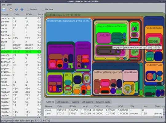
You can download the shaderfiles from here. Just an image of it in action: screenshot

The code where the magic happens (It's only long 'cos it's full of comments, but the code itself is max 50 lines):

void CylinderImpostor(out vec3 cameraPos, out vec3 cameraNormal)
{
    // First get the camera space direction of the ray.
    vec3 cameraPlanePos = vec3(mapping * max(cylRadius, cylHeight), 0.0) + cameraCylCenter;
    vec3 cameraRayDirection = normalize(cameraPlanePos);

    // Now transform data into Cylinder space wherethe cyl's symetry axis is up.
    vec3 cylCenter = cameraToCylinder * cameraCylCenter;
    vec3 rayDirection = normalize(cameraToCylinder * cameraPlanePos);


    // We will have to return the one from the intersection of the ray and circles,
    // and the ray and the side, that is closer to the camera. For that, we need to
    // store the results of the computations.
    vec3 circlePos, sidePos;
    vec3 circleNormal, sideNormal;
    bool circleIntersection = false, sideIntersection = false;

    // First check if the ray intersects with the top or bottom circle
    // Note that if the ray is parallel with the circles then we
    // definitely won't get any intersection (but we would divide with 0).
    if(rayDirection.y != 0.0){
        // What we know here is that the distance of the point's y coord
        // and the cylCenter is cylHeight, and the distance from the
        // y axis is less than cylRadius. So we have to find a point
        // which is on the line, and match these conditions.

        // The equation for the y axis distances:
        // rayDirection.y * t - cylCenter.y = +- cylHeight
        // So t = (+-cylHeight + cylCenter.y) / rayDirection.y
        // About selecting the one we need:
        //  - Both has to be positive, or no intersection is visible.
        //  - If both are positive, we need the smaller one.
        float topT = (+cylHeight + cylCenter.y) / rayDirection.y;
        float bottomT = (-cylHeight + cylCenter.y) / rayDirection.y;
        if(topT > 0.0 && bottomT > 0.0){
            float t = min(topT,bottomT);

            // Now check for the x and z axis:
            // If the intersection is inside the circle (so the distance on the xz plain of the point,
            // and the center of circle is less than the radius), then its a point of the cylinder.
            // But we can't yet return because we might get a point from the the cylinder side
            // intersection that is closer to the camera.
            vec3 intersection = rayDirection * t;
            if( length(intersection.xz - cylCenter.xz) <= cylRadius ) {
                // The value we will (optianally) return is in camera space.
                circlePos = cameraRayDirection * t;
                // This one is ugly, but i didn't have better idea.
                circleNormal = length(circlePos - cameraCylCenter) <
                               length((circlePos - cameraCylCenter) + cylAxis) ? cylAxis : -cylAxis;
                circleIntersection = true;
            }
        }
    }


    // Find the intersection of the ray and the cylinder's side
    // The distance of the point and the y axis is sqrt(x^2 + z^2), which has to be equal to cylradius
    // (rayDirection.x*t - cylCenter.x)^2 + (rayDirection.z*t - cylCenter.z)^2 = cylRadius^2
    // So its a quadratic for t (A*t^2 + B*t + C = 0) where:
    // A = rayDirection.x^2 + rayDirection.z^2 - if this is 0, we won't get any intersection
    // B = -2*rayDirection.x*cylCenter.x - 2*rayDirection.z*cylCenter.z
    // C = cylCenter.x^2 + cylCenter.z^2 - cylRadius^2
    // It will give two results, we need the smaller one

    float A = rayDirection.x*rayDirection.x + rayDirection.z*rayDirection.z;
    if(A != 0.0) {
        float B = -2*(rayDirection.x*cylCenter.x + rayDirection.z*cylCenter.z);
        float C = cylCenter.x*cylCenter.x + cylCenter.z*cylCenter.z - cylRadius*cylRadius;

        float det = (B * B) - (4 * A * C);
        if(det >= 0.0){
            float sqrtDet = sqrt(det);
            float posT = (-B + sqrtDet)/(2*A);
            float negT = (-B - sqrtDet)/(2*A);

            float IntersectionT = min(posT, negT);
            vec3 Intersect = rayDirection * IntersectionT;

            if(abs(Intersect.y - cylCenter.y) < cylHeight){
                // Again it's in camera space
                sidePos = cameraRayDirection * IntersectionT;
                sideNormal = normalize(sidePos - cameraCylCenter);
                sideIntersection = true;
            }
        }
    }

    // Now get the results together:
    if(sideIntersection && circleIntersection){
        bool circle = length(circlePos) < length(sidePos);
        cameraPos = circle ? circlePos : sidePos;
        cameraNormal = circle ? circleNormal : sideNormal;
    } else if(sideIntersection){
        cameraPos = sidePos;
        cameraNormal = sideNormal;
    } else if(circleIntersection){
        cameraPos = circlePos;
        cameraNormal = circleNormal;
    } else
        discard;
}   
Glorfindel
  • 21,988
  • 13
  • 81
  • 109
IceCool
  • 271
  • 2
  • 12
2

From what I can understand of the paper, I would interpret it as follows.

An impostor cylinder, viewed from any angle has the following characteristics.

  1. From the top, it is a circle. So considering you'll never need to view a cylinder top down, you don't need to render anything.
  2. From the side, it is a rectangle. The pixel shader only needs to compute illumination as normal.
  3. From any other angle, it is a rectangle (the same one computed in step 2) that curves. Its curvature can be modeled inside the pixel shader as the curvature of the top ellipse. This curvature can be considered as simply an offset of each "column" in texture space, depending on viewing angle. The minor axis of this ellipse can be computed by multiplying the major axis (thickness of the cylinder) with a factor of the current viewing angle (angle / 90), assuming that 0 means you're viewing the cylinder side-on.

Fig 1. Viewing angles. I have only taken the 0-90 case into account in the math below, but the other cases are trivially different.

Fig 2. 
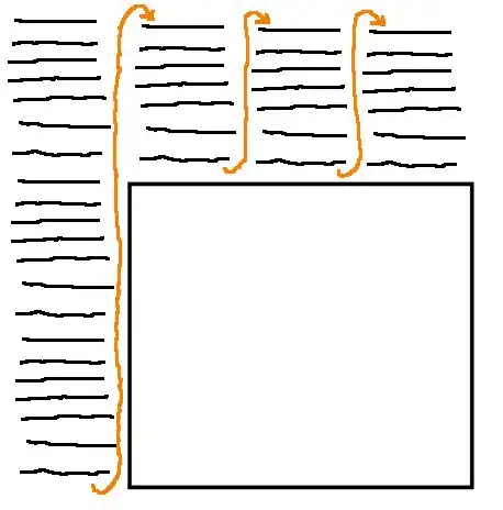
Given the viewing angle (phi) and the diameter of the cylinder (a) here's how the shader needs to warp the Y-Axis in texture space Y = b' sin(phi). And b' = a * (phi / 90). The cases phi = 0 and phi = 90 should never be rendered.

Of course, I haven't taken the length of this cylinder into account - which would depend on your particular projection and is not an image-space problem.

Ani
  • 10,826
  • 3
  • 27
  • 46
  • Thank you for the explanation, i understand a bit better my problem, but i always not see how to link all what you have said and implement it, so if you have time after to explain more in details it will be very helpful for me. in all case thanks for your precedent answer ! – nadir Mar 07 '12 at 18:39
  • Great thanks for your clear explanations, only i have few question, first what do you mean by "texture space" ? and for study these cases and find the viewing angle i think i will have need of "the normal" but my cylinder is only impostor and so the normal is computed in the fragment shader for every fragments, this is what it happen with sphere impostor, how to find this viewing angle without a normal ! – nadir Mar 09 '12 at 00:07
  • Simply put, texture space is (u,v) space - the space you work with inside a fragment shader. In the explanations above I have not considered lighting at all - all I explain is how to create curvature as the viewing angle changes (around the X-axis). I would recommend you get a basic cylinder impostor rendering without lighting first and then add that in later. – Ani Mar 09 '12 at 15:41