3

Original Question:

Problem

I have a unit cube that I would like to transform such that it connects two points. I am new to OpenGL and only know the most basic parts of linear algebra. I have attempted to mimic something similar to polar coordinates in my endeavor to connect the dots. My current implementation does not work when there is a change in Z and another axis. I also tried mat = glm::lookAt(center, terminal, y_axis);, but I did not have success.

Code

This comes from the body of a for loop located in schedule_edge_update().

auto const initial = p1;
auto const terminal = p2;
auto const distance = glm::distance(initial, terminal);
auto const length = distance * 0.5f;
auto const center = (initial + terminal) / 2.f;
auto const rejection = terminal - initial;
auto const delta = glm::normalize(rejection);

auto mat = glm::mat4(1);

// translate
mat = glm::translate(mat, center);

// rotate
auto const phi_hyp = glm::length(glm::vec2(delta.x, delta.z));
if (phi_hyp != 0.0f) {
    auto phi = acosf(delta.x / phi_hyp);
    mat = glm::rotate(mat, phi, y_axis);
}

auto const theta_hyp = glm::length(glm::vec2(delta.x, delta.y));
if (theta_hyp != 0.0f) {
    auto theta = acosf(delta.x / theta_hyp);
    theta *= delta.x > 0 ? -1.0f : 1.0f;
    mat = glm::rotate(mat, theta, z_axis);
}

// scale
edges->add_matrix(glm::scale(mat, glm::vec3(length, 0.05f, 0.01f)));

When a matrix is added to edges it is queued to be buffered for instanced rendering.

Far Away

Here are my testing points and a big cube I made. Far away

Close Up

Here is an example of it not working. The initial point is labeled p1 and the terminal point p2. The line that isn't connecting any points should be connecting p1 and p2.
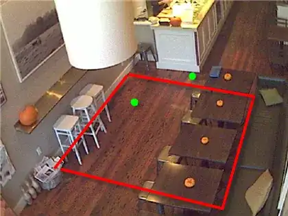
 Close up

Different Close Up

Here is another example, but this one has the coordinates for p1 and p2 labeled. p1 and p2 differ by a change in Y and Z. However, my code rotates the cube (after translating it) around the y axis 90 degrees. Then is scales it. You can tell it is rotated because it is wider on one of the axis (the y-axis before rotation). Different Close Up

Full List of Coordinates

// Test points
auto const A = glm::vec3(-10.0f, -10.0f, -20.0f);
auto const B = glm::vec3(+10.0f, -10.0f, -20.0f);
auto const C = glm::vec3(+10.0f, +10.0f, -20.0f);
auto const D = glm::vec3(+00.0f, +10.0f, -20.0f);
auto const E = glm::vec3(+05.0f, +05.0f, -20.0f);
auto const F = glm::vec3(+00.0f, +00.0f, -30.0f);
auto const G = glm::vec3(-10.0f, -10.0f, -30.0f);
auto const H = glm::vec3(+55.0f, -15.0f, -60.0f);
auto const I = glm::vec3(+55.0f, -05.0f, -70.0f);

get_nodes().emplace_back(A);
get_nodes().emplace_back(B);
get_nodes().emplace_back(C);
get_nodes().emplace_back(D);
get_nodes().emplace_back(E);
get_nodes().emplace_back(F);
get_nodes().emplace_back(G);
get_nodes().emplace_back(H);
get_nodes().emplace_back(I);

get_edges().emplace_back(A, B);
get_edges().emplace_back(B, C);
get_edges().emplace_back(C, D);
get_edges().emplace_back(D, E);
get_edges().emplace_back(E, F);
get_edges().emplace_back(F, G);
get_edges().emplace_back(G, H);
get_edges().emplace_back(H, I);

// Big cube
auto const C0 = glm::vec3(-5.0f, -5.0f, -5.0f);
auto const C1 = glm::vec3(-5.0f, -5.0f, +5.0f);
auto const C2 = glm::vec3(-5.0f, +5.0f, -5.0f);
auto const C3 = glm::vec3(-5.0f, +5.0f, +5.0f);
auto const C4 = glm::vec3(+5.0f, -5.0f, -5.0f);
auto const C5 = glm::vec3(+5.0f, -5.0f, +5.0f);
auto const C6 = glm::vec3(+5.0f, +5.0f, -5.0f);
auto const C7 = glm::vec3(+5.0f, +5.0f, +5.0f);

get_nodes().emplace_back(C0);
get_nodes().emplace_back(C1);
get_nodes().emplace_back(C2);
get_nodes().emplace_back(C3);
get_nodes().emplace_back(C4);
get_nodes().emplace_back(C5);
get_nodes().emplace_back(C6);
get_nodes().emplace_back(C7);

get_edges().emplace_back(C0, C1);
get_edges().emplace_back(C0, C2);
get_edges().emplace_back(C0, C4);
get_edges().emplace_back(C1, C3);
get_edges().emplace_back(C1, C5);
get_edges().emplace_back(C2, C3);
get_edges().emplace_back(C2, C6);
get_edges().emplace_back(C3, C7);
get_edges().emplace_back(C4, C5);
get_edges().emplace_back(C4, C6);
get_edges().emplace_back(C5, C7);
get_edges().emplace_back(C6, C7);

schedule_node_update();
schedule_edge_update();

Spektre's Solution Using GLM

Code

auto constexpr A = vec3(-0.5f, 0.0f, 0.0f);
auto constexpr B = vec3(+0.5f, 0.0f, 0.0f);
auto const C = p1;
auto const D = p2;

auto M = mat4(1.0f);

// Translate
auto const center = 0.5 * (C + D);
M = translate(M, center);

// Rotate
auto constexpr p = B - A;
auto const q = D - C;
auto const n = cross(p, q);
if (n != vec3()) {
    auto const a = angle(normalize(p), normalize(q));
    M = rotate(M, a, n);
}

// Scale
auto constexpr thickness = 0.05f;
M = scale(M, vec3(0.5f * distance(C, D), thickness, thickness));

edges->add_matrix(M);

Successful Result

Successful Result

user1032677
  • 363
  • 2
  • 11
  • 1
    its unclear what you want to achieve! What do you mean by joining 2 points by matrix? which points? are you perhaps constructing the cube similarly to turtle graphics? Matrix does not join anything it can position,orient and scale some geometry. I do not see relevant code in your sample there is no rendering I see no geometry I see no control code (that would explain what you trying to do) . Please edit your question a bit to make it more clear.... – Spektre Apr 24 '20 at 07:33
  • @Spektre I am trying to move a unit cube from the origin between two nodes. Then rotate and scale it so that it connects the nodes. https://imgur.com/a/U2nxItB I can link the repo, but the control code is pretty large. The cube and sphere are loaded in through .obj files. – user1032677 Apr 24 '20 at 07:56
  • 1
    so you want that diagonal of your cube is start/ending on the 2 points? Do you know the cube center, size, orientation (idealy the 2 diagonal points positions)? also the 2 points you want the cube hit? – Spektre Apr 24 '20 at 08:04
  • @Spektre Yes, the cube starts off as a unit cube at the origin. I also know where the points p1 and p2 are and can translate the cube to the center of them and scale the cube to the perfect length to touch them if it was rotated correctly. – user1032677 Apr 24 '20 at 08:08
  • 1
    so the axis aligned cube is 1. centered around `(0,0,0)` and side length is `1` or `2` or 2. `(0,0,0)` is one diagonal point and `(1,1,1)` is the other one? Your image suggest the latter. – Spektre Apr 24 '20 at 08:09
  • @Spektre The big cube in the picture is 10x10x10 centered at (0,0,00. I added all of the coordinates for every point at the bottom of the post. – user1032677 Apr 24 '20 at 08:17
  • will try to make some example ... but it will take me a while ... Also I do not use GLM so you would need to translate the vector math to GLM function names. also from the points your cube is not centered by (0,0,0) but as I got the diagonals that suffice ... – Spektre Apr 24 '20 at 08:20
  • @Spektre Why is the big cube (C0-C7, lower half of the coordinate list) not centered at (0, 0, 0)? – user1032677 Apr 24 '20 at 08:31
  • Ow I saw the ABCDEFGH ... so `C?` is the cube in question ... – Spektre Apr 24 '20 at 08:32
  • 2
    I manage to finish editing see my answer. – Spektre Apr 24 '20 at 10:36
  • @Spektre, Worked like a charm. The only change I made was skipping the rotation if the normal was zero. If you could post anything thing over [here](https://math.stackexchange.com/q/3638035/755390), I would like to accept this answer on the math stack. – user1032677 Apr 24 '20 at 18:21
  • I do not participate at Math SE not a math guy and barely have any time to maintain my other SE accounts (mostly active in here) ... If you want you can answer yourself (and link this QA to it with comment that the answer is based on it or something like that ...) – Spektre Apr 24 '20 at 22:00

1 Answers1

5

So the problem boils down to this:

I know 4 points A,B,C,D and I want to compute transform matrix that will convert A,B into C,D.

overview

This can be done like this. Let assume we convert points like this:

M * A = C
M * B = D

Where M is out transform matrix we want to compute. There are infinite number of possible solutions (as the line AB can have any rotation on its own axis)

If you dissect the M a bit its just a matter of knowing position, orientation and scale.

  1. Scale is the simplest

    its just the ratio of the line length after and before transformation.

    scale = |CD|/|AB|
    
  2. orientation

    its represented by unit basis vectors. We can exploit the fact that the AB and CD has just single rotation (all others just produce the infinite number of solutions) so we can just rotate AB by the angle between AB,CD around axis perpendicular to both AB,CD. The angle we can obtain by acos of dot product between unit vectors parallel to AB,CD. The only problem is that will not give us direction of rotation so we need to test the two possibilities (CW,CCW).

    so:

     axis  = cross(B-A,D-C)
     angle = +/- acos(dot(B-A,D-C) / |B-A|*|D-C|)
    
  3. translation

    this one is simple we just transform A with M without translation lets call it A' and then just correct the resulting position so it goes to C.

    M_origin += C-A'
    

    Beware that the translation should be set directly, not applying translation matrix. Those usually translate in local coordinate system [LCS] which involves converting the difference to it first. In such case use

    translate(Inverse(M)*(C-A'))
    

    or

    translate(M*(C-A'))
    

    depending on used notations.

Here small C++/VCL/old GL example:

//---------------------------------------------------------------------------
#include <vcl.h>
#include <math.h>
#pragma hdrstop
#include "Unit1.h"
#include "gl_simple.h"
#include "OpenGLrep4d_double.h"
//---------------------------------------------------------------------------
#pragma package(smart_init)
#pragma resource "*.dfm"
TForm1 *Form1;
//---------------------------------------------------------------------------
double arot=0.0;                // just animation angle
//---------------------------------------------------------------------------
const int pnts=8;
double pnt[pnts*3]=             // Vertexes for 10x10x10 cube centered at (0,0,0)
    {
    -5.0,-5.0,-5.0,
    -5.0,+5.0,-5.0,
    +5.0,+5.0,-5.0,
    +5.0,-5.0,-5.0,
    -5.0,-5.0,+5.0,
    -5.0,+5.0,+5.0,
    +5.0,+5.0,+5.0,
    +5.0,-5.0,+5.0,
    };
const int lins=12;
int lin[lins*2]=                // lines (index of point used) no winding rule
    {
    0,1,1,2,2,3,3,0,
    4,5,5,6,6,7,7,4,
    0,4,1,5,2,6,3,7,
    };
double A[3]={-5.0,-5.0,-5.0};   // cube diagonal
double B[3]={+5.0,+5.0,+5.0};
double C[3]={-4.5, 2.0, 0.0};   // wanted cube diagonal
double D[3]={+4.5, 5.0, 0.0};
double M[16];                   // our transform matrix
//---------------------------------------------------------------------------
void compute_M()
    {
    double scale,p[3],q[3],n[3],a;
    const double deg=180.0/M_PI;
    const double rad=M_PI/180.0;
    glMatrixMode(GL_MODELVIEW);
    glPushMatrix();

    // scale
    vector_sub(p,B,A);                      // p=B-A
    vector_sub(q,D,C);                      // q=D-C
    scale=vector_len(q)/vector_len(p);      //  =|q|/|p|

    // rotation between AB and CD
    vector_mul(n,p,q);                      // n = (p x q) ... cross product
    vector_one(p,p);                        // p = p/|p|
    vector_one(q,q);                        // q = q/|q|
    a=acos(vector_mul(p,q));                // angle between AB and CD in [rad]

    glLoadIdentity();                       // unit matrix
    glRotated(+a*deg,n[0],n[1],n[2]);       // rotate by angle around normal to AB,CD
    glScaled(scale,scale,scale);            // apply scale
    glGetDoublev(GL_MODELVIEW_MATRIX,M);    // get the M from OpenGL

    // translation
    matrix_mul_vector(p,M,A);               // p = M*A
    vector_sub(p,C,p);                      // p = C-p
    M[12]=p[0];
    M[13]=p[1];
    M[14]=p[2];
    M[15]=1.0;

    // verify
    matrix_mul_vector(p,M,B);               // p = M*B
    vector_sub(p,p,D);                      // p = p-C
    if (vector_len(p)>1e-3)                 // if |p| too big use other direction to rotate
        {
        glLoadIdentity();                       // unit matrix
        glRotated(-a*deg,n[0],n[1],n[2]);       // rotate by angle around normal to AB,CD
        glScaled(scale,scale,scale);            // apply scale
        glGetDoublev(GL_MODELVIEW_MATRIX,M);    // get the M from OpenGL
        }

    glPopMatrix();
    }
//---------------------------------------------------------------------------
void gl_draw()      // main rendering code
    {
    int i;
    double m0[16],m1[16],m[16],x[3],y[3],z[3],t2[3][3];

    glClear(GL_COLOR_BUFFER_BIT | GL_DEPTH_BUFFER_BIT);
    glDisable(GL_CULL_FACE);
    glEnable(GL_DEPTH_TEST);

    glMatrixMode(GL_MODELVIEW);
    glLoadIdentity();
    glTranslated(0.0,0.0,-50.0);
    glRotated(15.0,1.0,0.0,0.0);
    glRotated(arot,0.0,1.0,0.0);

    glBegin(GL_LINES);
    glColor3f(1.0,0.0,0.0); for (i=0;i<lins*2;i++) glVertex3dv(pnt+(lin[i]*3)); // render original cube
    glColor3f(0.0,1.0,0.0); glVertex3dv(A); glVertex3dv(B);                     // render original diagonal AB
    glColor3f(1.0,1.0,0.0); glVertex3dv(C); glVertex3dv(D);                     // render wanted diagonal CD
    glEnd();

    // render transformed cube
    glMatrixMode(GL_MODELVIEW);
    glMultMatrixd(M);
    glBegin(GL_LINES);
    glColor3f(0.0,0.0,1.0); for (i=0;i<lins*2;i++) glVertex3dv(pnt+(lin[i]*3)); // render transformed cube
    glEnd();


    glFlush();
    SwapBuffers(hdc);
    }
//---------------------------------------------------------------------------
__fastcall TForm1::TForm1(TComponent* Owner):TForm(Owner)
    {
    // application init
    gl_init(Handle);
    compute_M();
    }
//---------------------------------------------------------------------------
void __fastcall TForm1::FormDestroy(TObject *Sender)
    {
    // application exit
    gl_exit();
    }
//---------------------------------------------------------------------------
void __fastcall TForm1::FormResize(TObject *Sender)
    {
    // window resize
    gl_resize(ClientWidth,ClientHeight);
    }
//---------------------------------------------------------------------------
void __fastcall TForm1::FormPaint(TObject *Sender)
    {
    // window repaint
    gl_draw();
    }
//---------------------------------------------------------------------------
void __fastcall TForm1::Timer1Timer(TObject *Sender)
    {
    arot+=1.5; if (arot>=360.0) arot-=360.0;
    gl_draw();
    }
//---------------------------------------------------------------------------

Just ignore the VCL related stuff. The GL support functions you can find in here:

The only important stuff here is the compute_M() along with the global variables.

The vector math functions are commented (so you can translate that to GLM) if you need implementations you can find those in the linked QA above. It basically takes. For simplicity I used GL native rotations (beware they are in degrees instead of radians).

Here preview:

preview

  • red is original cube
  • green is original diagonal AB
  • blue is transformed cube by M
  • yellow is wanted diagonal CD

As you can see it matches.

In case you need to align more than just a line you need add more info for aligning (2 lines (3 points) for example) etc. For more info see:

Spektre
  • 49,595
  • 11
  • 110
  • 380